BMX EHC 0200 Module Operation in Free Large Counter Mode
Original instructions
At a Glance
The use of the free large counter mode is especially recommended for axis monitoring or labeling where the incoming position of each part has to be learned.
Basic Principle
The upcounting (or downcounting) starts as soon as the homing function is completed.
The enable function must be activated during the counting by:
When the enable function is deactivated, the last value reported in the counting register is maintained and the counter ignores the pulses applied to the IN_A input. However, it does not ignore the preset condition.
In the free large counter mode, the counter must be preset at least one time to operate. The current counter value is load with the preset_value each time the preset condition occurs.
The current counter can be recorded into the capture0 register when the preset condition occurs or using the IN_CAP input.
The current counter value can be stored into the capture1 register using the IN_CAP input.
For further information, you may see the synchronization function and the capture function.
In the free large counter mode, the counting register is updated at 1 ms intervals.
Counting Configurations
In this mode, the user may select one of the following counting configurations:
The following table shows the upcounting and downcounting principle according to the selected configuration:
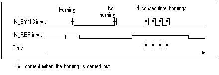
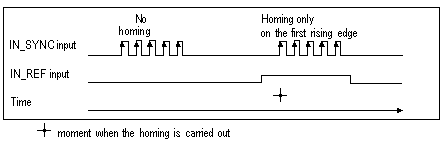
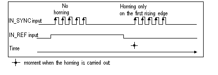
Selected configuration
Upcounting condition
Downcounting condition
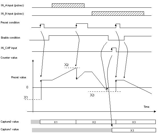
A = Up, B = Down
Rising edge at the IN_A input.
Rising edge at the IN_B input.
A = Impulse, B = Direction
Rising edge at the IN_A input and low state at the IN_B input.
Rising edge at the IN_A input and high state at the IN_B input.
Normal Quadrature X1
Rising edge at the IN_A input and low state at the IN_B input.
Falling edge at the IN_A input and low state at the IN_B input
Normal Quadrature X2
Rising edge at the IN_A input and low state at the IN_B input.
Falling edge at the IN_A input and high state at the IN_B input.
Falling edge at the IN_A input and low state at the IN_B input.
Rising edge at the IN_A input and high level at the IN_B input.
Normal Quadrature X4
Rising edge at the IN_A input and low state at the IN_B input.
High state at the IN_A input and rising edge at the IN_B input.
Falling edge at the IN_A input and high state at the IN_B input.
Low state at the IN_A input and falling edge at the IN_B input.
Falling edge at the IN_A input and low state at the IN_B input.
Low state at the IN_A input and rising edge at the IN_B input.
Rising edge at the IN_A input and high level at the IN_B input.
High state at the IN_A input and falling edge at the IN_B input.
Reserve Quadrature X1
Falling edge at the IN_A input and low state at the IN_B input.
Rising edge at the IN_A input and low state at the IN_B input.
Reserve Quadrature X2
Falling edge at the IN_A input and low state at the IN_B input.
Rising edge at the IN_A input and high level at the IN_B input.
Rising edge at the IN_A input and low state at the IN_B input.
Falling edge at the IN_A input and high state at the IN_B input.
Reserve Quadrature X4
Falling edge at the IN_A input and low state at the IN_B input.
Low state at the IN_A input and rising edge at the IN_B input.
Rising edge at the IN_A input and high level at the IN_B input.
High state at the IN_A input and falling edge at the IN_B input.
Rising edge at the IN_A input and low state at the IN_B input.
High state at the IN_A input and rising edge at the IN_B input.
Falling edge at the IN_A input and high state at the IN_B input.
Low state at the IN_A input and falling edge at the IN_B input.
Homing Function
This function allows to record the current_counter_value register in the capt_0_val register and/or to set the current_counter_value register to the user-predefined parameter preset_value.
The value defined by the user as preset_value is contained in the %MDr.m.c.4 word.
The user may change this value by specifying the value of this word:
For further information, you may see the homing function and the capture function.
The module configuration enables you to select the following homing conditions:


Operation
The trend diagram below illustrates the counting process for a free large counter in the configuration by default:
Behavior at the Counting Limits
When the upper or lower limit is exceeded, the counter behaves differently according to its configuration.
In the lock on limits default configuration, the counting register maintains the limit value once it has been reached and the counting validity bit changes to 0 until the next preset condition occurs:
NOTE: Overflow or underflow is indicated by two bits LOW_LIMIT and HIGH_LIMIT until the application reloads the counting value predefined by the user (force_ref bit set to 1 or preset condition true). The upcounting or downcounting may therefore resume.
In the rollover configuration, the counting register switches to the opposite limit value when one of the two limits is exceeded:
Slack Delete
In the free large counter mode, the counter may apply a hysteresis if the rotation is inverted. The hysteresis parameter configured with the adjust screen defines the number of points that are not acknowledged by the counter during the rotation inversion. This aims to take into account the slack between the encoder/motor axis and the mechanical axis (e.g. an encoder measuring the position of a mat).
This behavior is described in the following figure:
The value defined by the user as the Hysteresis (slack) value is contained in the %MWr.m.c.9 word. The user may change this value by specifying the value of this word (this value is from 0 to 255):
Counter Status Bits in Free Large Counter Mode
The table below shows the composition of the counter’s %IWr.m.c.0 status word in free large counter mode:
Bit
Label
Description
%IWr.m.c.0.1
MODULO_FLAG
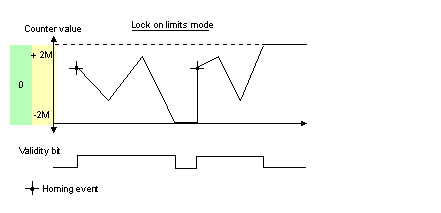
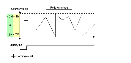
The bit status changes in the rollover mode.
The bit is set to 1 when the counter rollovers its limits (-2,147,483,648 or +2,147,483,647).
The bit is reset to 0 when the command MODULO_RESET (%Qr.m.c.9) is received (rising edge of the MODULO_RESET bit).
%IWr.m.c.0.2
SYNC_REF_FLAG
The bit is set to 1 when the counter have been set to the preset value and (re)started.
The bit is reset to 0 when the command SYNC_RESET (%Qr.m.c.8) is received (rising edge of the SYNC_RESET bit).
%IWr.m.c.0.3
VALIDITY
Validity bit is used to indicate that the counter current value and compare status registers contain valid data.
If the bit is set to 1, the data is valid.
If the bit is set to 0, the data is not valid.
%IWr.m.c.0.4
HIGH_LIMIT
The bit status changes in the lock on limits mode.
The bit is set to 1 when the counter reaches +2,147,483,647.
The bit is reset to 0 when the counter presets or resets.
%IWr.m.c.0.5
LOW_LIMIT
The bit status changes in the lock on limits mode.
The bit is set to 1 when the counter reaches -2,147,483,648.
The bit is reset to 0 when the counter presets or resets.
Type of the IODDT
In this mode, the type of the IODDT must be T_SIGNED_CPT_BMX.
Operating Limits
The shortest pulse applied to the IN_SYNC input is 100 μs.
The maximum homing event frequency is once every 5 ms.
The counter value is between -2,147,483,648 and +2,147,483,647.
NOTE: You have to check the validity bit (%IWr.m.c.0.3) before taking into account the numerical values such as the counter and the capture registers. Only the validity bit at the high level (set to 1) guarantees that the mode will operate correctly within the limits.