Using the one shot counter mode allows you to quantify a group of parts.
In this mode, activating the synchronization function starts the counter which, starting from a value defined by the user in the adjust screen (preset value), decreases with every pulse applied to the IN_A input until it reaches the value 0. Downcounting is made possible when the enable function is activated. The counting register is thus updated every 1 ms.
One basic use of this mode is, using an output, to indicate the end of a group of operations (when the counter reaches 0).
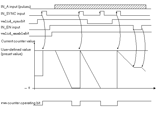
The trend diagram below illustrates the counting process in one shot counter mode:
In the trend diagram above, we can see that the counter is set to the preset value at the IN_SYNC input’s rising edge. Then, the counter decrements the counting register with every pulse applied to the IN_A input. When the register is set to 0, the counter awaits a new signal from the IN_SYNC input. The IN_A input pulses have no effect on the register value as long as the counter is set to 0.
The enable function must be activated during the counting by:
When the enable function is deactivated, the last value reported in the counting register is maintained and the counter ignores the pulses applied to the IN_A input. However, it does not ignore the IN_SYNC input status.
Each time the counter starts a downcounting operation, the run bit switches to the high level. It switches to the low level when the register value reaches 0.
NOTE: The pulses applied to IN_SYNC and IN_EN inputs are only taken into account when the inputs are
enabled.
The value defined by the user (preset value) is contained in the word %MDr.m.c.6. The user may change this value by specifying the value of this word by configuring the parameter in the adjust screen or by using the WRITE_PARAM(IODDT_VAR1) Function. IODDT_VAR1 is of the type T_UNSIGNED_CPT_BMX. This value change is only taken into account by the module after one of the following conditions has been established:
Counter Status Bits in One shot Counter Mode
The table below shows bits that are used by the status word %IWr.m.c.0 when the counter is configured in one shot counter mode:
|
Bit
|
Label
|
Description
|
|
%IWr.m.c.0.0
|
RUN
|
The bit is set to 1 when the counter is running.
The bit is set to 0 when the counter is stopped.
|
|
%IWr.m.c.0.2
|
SYNC_REF_FLAG
|
The bit is set to 1 when the counter has been set to the preset value and (re)started.
The bit is reset to 0 when the sync_reset command is received (rising edge of the %Qr.m.c.8 bit).
|
|
%IWr.m.c.0.3
|
VALIDITY
|
Validity bit is used to indicate that the counter current value and compare status registers contain valid data.
If the bit is set to 1, the data is valid.
If the bit is set to 0, the data is not valid.
|
In this mode, the type of the IODDT must be T_UNSIGNED_CPT_BMX.
The maximum frequency that can be applied to the IN_SYNC input is 1 pulse every 5 ms.
The maximum value defined by the user (preset value) is 4,294,967,295.
NOTE: You have to check the validity bit (%IWr.m.c.0.3) before taking into account the numerical values such as the counter and the capture registers. Only the validity bit at the high level (set to 1) guarantees that the mode will operate correctly within the limits.