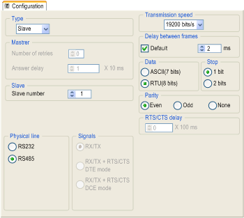
Modbus Serial Communication Configuration Screen
(Original Document)
General
The following pages provide an introduction to the configuration screen for Modbus serial communication.
Access to the Configuration Screen
To access the Modbus serial communication configuration screen, open the Serial Port directory in the project browser.
Modbus Serial Communication Configuration Screen
The following figure shows the configuration screen for Modbus serial communication:
Description
These zones are used to configure channel parameters. In online mode, these zones are accessible. In offline mode, the zone is accessible but some parameters may not be accessible and are grayed out.
The following table shows the different zones of the Modbus link configuration screen:
Element
Comment
These parameters are accessible via three zones:
  • Type,
  • Master,
  • Slave.
These parameters are accessible via three zones:
  • Physical line,
  • Signals,
  • RTS/CTS delay.
These parameters are accessible via five zones:
  • Transmission speed,
  • Delay between frames,
  • Data,
  • Stop bits,
  • Parity.
NOTE: When configuring Modbus Serial communication in master mode, the Slave zone is grayed out and cannot be modified and conversely.
Default Values
The following table shows the default values for Modbus Serial communication parameters:
Configuration parameters
Value
Application parameters
Type
Slave
Slave number
1
Signal and physical line parameters
Physical line
RS485
Signals
RX/TX
Transmission parameters
Transmission speed
19200 bits/s
Delay between frames
2 ms
Data
RTU (8 bits)
Stop
1 bit
Parity
Even