The transmission parameters are accessible from five zones:
-
The Transmission speed zone,
-
The Delay between frames zone,
-
The Data zone,
-
The Stop zone,
-
The Parity zone.
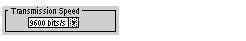
The
Transmission speed Zone
This configuration zone appears on the screen as shown below:
You can use it to select the transmission speed of the Modbus Serial. The selected speed has to be consistent with the other devices. The configurable values are 300, 600, 1200, 2400, 4800, 9600, 19200 and 38400 bits per second.
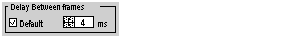
The
Delay between frames Zone
This configuration zone appears on the screen as shown below:
The Delay between frames is the minimum time separating two frames on reception. This delay is managed when the PLC (master or slave) is receiving messages.
NOTE: The default value depends on the selected transmission speed.
NOTE: The delay between frames should be the Default value in order to be Modbus compliant. In case a Slave is not conform, the value can be changed and should be identical for the Master and all Slaves on the Bus.
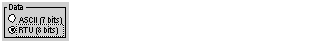
This configuration zone appears on the screen as shown below:
This zone allows you to enter the type of coding used to communicate using Modbus Serial. This field is set according to the other devices connected on the bus. There are two configurable modes:
-
RTU mode:
-
The characters are coded over 8 bits.
-
The end of the frame is detected when there is a silence of at least 3.5 characters.
-
The integrity of the frame is checked using a word known as the checksum, which is contained within the frame.
-
ASCII mode:
-
The characters are coded over 7 bits.
-
The beginning of the frame is detected when the ":" character is received.
-
The end of the frame is detected by a carriage return and a line feed.
-
The integrity of the frame is checked using a byte called the checksum, which is contained within the frame.
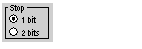
This configuration zone appears on the screen as shown below:
The Stop zone allows you to enter the number of stop bits used for communication. This field is set according to the other devices. The configurable values are:
This configuration zone appears on the screen as shown below:
This zones enables you to determine whether a parity bit is added or not, as well as its type. This field is set according to the other devices. The configurable values are: