|
Module configuration screen
|
|


|
(Original Document)
|
|
Module configuration screen
|
|
|
(Original Document)
|
|
Address
|
Element
|
Function
|
|---|---|---|
|
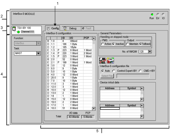
1
|
Tabs
|
The tab in the foreground shows the current mode (Configuration for this example). Each mode can be selected by means of the corresponding tab. The available modes are:
|
|
2
|
Module zone
|
Shows the short name of the module and the state of the module online by LEDs.
|
|
3
|
Channel field
|
Is used:
|
|
4
|
General parameters field
|
Allows you to choose the general parameters associated with the channel :
|
|
5
|
Configuration zone
|
Allows you to configure the channel's configuration parameters. Certain choices may be frozen and appear grayed out.
It is broken down into six zones:
|

 ) and to the CMD Tool software (button
  ),
),