Introduction
IEC60870-5 is an international standard released in the early 1990s by the International Electrotechnical Commission (IEC). This standard provides a communication profile for telecontrol, teleprotection, and associated telecommunications characteristics for electric power systems. It is widely used today for other infrastructures, including water applications in Europe and Asia.
The IEC60870-5-101 and IEC60870-5-104 protocols are designed for systems that have permanent direct connections between the controlling station (client) and the controlled station(s) (servers). The IEC60870-5-101 and IEC60870-5-104 standards are applicable for multiple network configurations like point-to-point, star, and multi-drop. The standard is suitable for power system monitoring, control communications, teleprotection, and associated telecommunications for electric power systems.
Protocol Distinctions
The IEC60870-5-104 protocol is an extension of the IEC60870-5-101 protocol. There are changes in transport, network, link & physical layer to open networking.
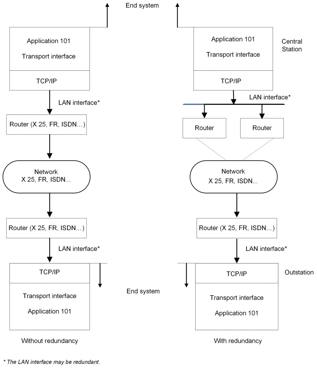
IEC60870-5-104 enables communication between control stations and substations in a standard TCP/IP network. The TCP protocol is used for connection-oriented data transmission. To have connectivity to LANs and routers with different facilities (frame relay, etc.), connect it to the WAN. The application layer of IEC60870-5-104 is the same as that of IEC60870-5-101, except that some data types and facilities are not used. There are separate link layers defined in the standard, which facilitates the transfer of data over Ethernet and serial lines.
Supported Protocol Features
Feature |
Description |
|---|---|
link mode |
|
data classification |
|
data update |
Cyclic and spontaneous updating methods can be used. |
Feature |
Description |
|---|---|
general interrogation |
A general interrogation command retrieves a specified group of static data from a remote outstation. It is typically sent after device restart, loss of communication, or on a periodic basis so that no changes are missed in the spontaneous reporting of data. |
time synchronization |
The time synchronization service establishes time accuracy among devices clocks over a network. |
events transmission (time-stamped or not) |
Configure the transmission threshold based on the count or time since the last event transmission. |
counter interrogation |
Counter-interrogation commands retrieve counter values from the RTU. |
command transmission modes (select and execute mode) |
select/execute: Write operations with a dual command and response. |
execute: Write operations with a single command and response. |
Supported Data Types
discrete inputs/outputs (single or double)
measured values (with different formats)
integrated totals
commands
step position
bit string
Protocol Characteristics
The table lists the characteristics for the supported RTU protocols:
Protocol |
Characteristics |
|---|---|
IEC60870-5-104 server |
client IP address validation list (up to 10 IP addresses) |
up to four concurrent client connections with configurable TCP service port (standard is 2404) |
|
Input and output maximum (module
level):
NOTE: Refer to the description of I/O data exchange with the CPU.
|
|
up to 150,000 events in a queue for all data types in all clients (each client has a dedicated event buffer) |
|
event time-stamping configurable by type (None, CP56) |
|
channel redundancy |
|
IEC60870-5-104 client |
|
up to 64 server connections supported |
|
connections share common channel configuration |
|
dedicated connection for each device configuration |
|
dedicated destination IP address and port settings for each connection |
|
IEC60870-5-101 slave |
|
up to 150,000 events in a queue for all data types in all clients (each client has a dedicated event buffer) |
|
event time-stamping configurable by type (None, CP56) |
|
Maximum number of active connections: 1 Maximum number of configured sessions: 1 |
|
IEC60870-5-101 master |
|
Maximum number of active connections:
|
|
connections share common channel configuration |
|
dedicated connection for each device configuration |
Channel Redundancy
Redundancy is sometimes necessary to increase the availability of the communication system. In these cases, confirm that you establish multiple redundant connections between the two stations. Redundant communication in a system using IEC60870-5-104 allows you to establish more than one logical connection between two stations. A logical connection is defined by a unique combination of two IP addresses and two port numbers, specifically the controlling station’s IP address/port number pair and the controlled station’s IP address/port number pair.
Application Layer |
|||
Redundancy Group or Channel |
|||
Channel 1 |
Channel 2 |
Channel 3 |
|
This flowchart shows the general architecture for a redundant configuration in the central station as well as a non-redundant system:

Every main or virtual channel can be configured as None, which indicates the independence of the channel. That is, it does not belong to any redundancy group.
Every main or virtual channel can be configured as group 1/2/3.
There is only one Active channel in one redundant group. It performs all user application communications. All the other connected channels are inactive. (Inactive channels are monitored to confirm that they are operational.)
If an active link control is configured as External when the active channel stops communicating, its communications move to the next operational channel by a remote client via a STARTDT message.
- If an active link control is configured as Module when the active channel stops communicating, the module automatically moves its communications to the next operational channel.NOTE: For the Event Backup restore mode, we recommend that you select All Channels for the Restore Mode in the channel configuration.


