About Dual-Bus Backplanes

The dual-bus interface on the back of the BMENOR2200H module connects to the X Bus and Ethernet bus connectors across the backplane when you mount the module in the rack.

BMEXBP••0• backplanes are compatible with Modicon X80 modules in an M580 system.

Communications across the dual-bus backplane of this sample local rack (which includes an M580 CPU) implement both the Ethernet (red line) and X-Bus (blue line) protocols:
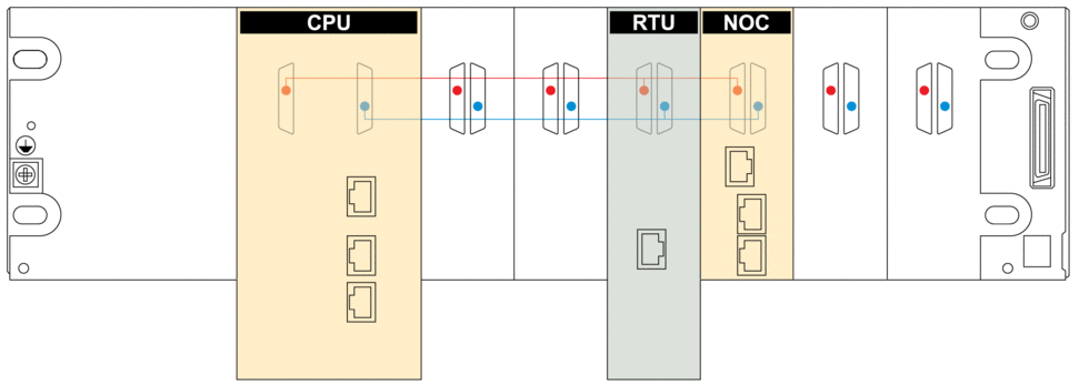
Red The red dot/line indicates Ethernet.

Blue The blue dot/line indicates X Bus.

NOTE:
  • BMXXPB••00 X Bus backplanes do not have connections that support eX80 modules.

  • Ethernet racks are described in detail in the Modicon M580, Hardware, Reference Manual.

Connection Protocols

The module supports communications over a BMEXBP••0• backplane using these protocols:

Bus

Description

X Bus

The module uses X Bus communications to obtain and exchange the following through the CPU:

  • configuration data for the module

  • application and Device DDT diagnostic data

  • download the PLC application to the CPU via the BMENOR2200H module when the Modbus service is enabled.

  • variable data exchange between the module and the CPU

  • time synchronization messages to the CPU and other modules on the backplane

Ethernet

NOTE: The Ethernet backplane port is always enabled for the BMENOR2200H module. Confirm your network topology design to help avoid network loop issues.

The module uses Ethernet communications to provide an access path to the BMENOR2200H module for the following:

  • External devices can talk with the BMENOR2200H module when accessing one of the following:

    • CPU

    • BMENOC03•• communication module

    • BMENOS0300 network option switch module

    • BM•CRA312•• adapter

    • other Ethernet modules with similar capabilities

  • The module communicates with Ethernet communication modules on the local rack.

The data exchange uses implicit messaging to facilitate memory sharing between the module and the CPU. For each CPU scan cycle, the CPU publishes all data at the same time to share the most current information with the RTU.

I/O Data Exchange with the CPU

Observe these maximum input and output sizes when the module exchanges I/O data with the CPU:

Protocol

Characteristics

  • IEC 60870-5-101

  • IEC 60870-5-104

  • DNP3

Memory consumption:

  • input data size: 8 Kb of data includes user-configurable data and 4K words of overhead. The overhead includes module diagnostic data, data object headers, and the number of headers depending on the user configuration. As a result, the maximum user-configurable input data size is approximately 7.55Kb (1Kb = 1024 bytes).

  • output data size: 8 Kb of data includes user-configurable data and 4K words of overhead. The overhead includes module control data, data object headers, and the number of headers depending on the user configuration. As a result, the maximum user-configurable output data size is approximately 7.56Kb (1Kb = 1024 bytes).

NOTE:
  • You can view the memory usage in the Control Expert DTM (Generation > Module Information > Memory Status ). Refer to the description of module information in the DTM.

    NOTE: Refer to the description of the module information in the DTM.
  • Concerning the 8 Kb input and output sizes, the exact memory consumption depends on the type of data mapping to the CPU; different data types consume different amounts of memory.

Minimum MAST Cycle Time

Use this formula to achieve the recommended minimum MAST task cycle time for a single BMENOR2200H module:

Tcycle min= ((DataInB + 128)*2+(DataOutB + 32)) / 23500B/S)*30ms

The result is approximately a 30ms MAST task cycle with 8Kb in and 8Kb out.

NOTE: When more than one BMENOR2200H RTU module is installed, the minimum cycle time is the sum of the cycle times for all modules.