Overview

Use this tab to configure memory management for the selected input / output module. Memory management is performed by configuring State RAM. Topological addressing is not supported.

State RAM Configuration for Discrete Modules

Depending on the selected discrete I/O module, the State RAM area of the Memory tab contains parameters for discrete input modules, discrete output modules or for discrete mixed modules.

The figure below shows the Memory tab for a discrete mixed input / output module as an example:
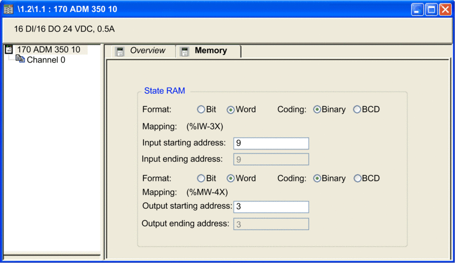
The State RAM area contains the following parameters:

Parameter

Description

Format

  • Bit: Select this option for channel mapping in the discrete mode. This means that each channel is mapped to a %I (inputs) or %M (outputs).

  • Word1: Select this option for channel mapping in the word mode. This means that a group of 8 channels is mapped to a %IW (inputs) or %MW (outputs).

Coding

This parameter is only available for channel mapping in word mode when the parameter Format is set to Word.

  • Binary: Select this option to use the binary integer format.

  • BCD: Select this option to use the BCD coding format.

Mapping

This parameter allows you to define the starting address for the inputs and outputs.

The following sizes of the memory areas are possible:

  • For inputs in Bit format: %I-1x

  • For inputs in Word format: %IW-3x

  • For outputs in Bit format: %M-0x

  • For outputs in Word format: %MW-4x

NOTE: The State RAM address starts at address 0, but the first available address for discrete and analog modules is %I1, %M1, %IW1, and %MW1.

1. When Word is selected as the Format, the LSB of the Word is mapped to:

  • Input 0 on discrete input modules

  • Output 0 on discrete output modules

NOTE: Configure every channel of a discrete module. You cannot leave a group of channels in their non-configured state.
NOTE: You can use State RAM objects in event sections. They are refreshed with the frequency of the task where they are declared.
NOTE: State RAM addresses are not checked during input. If any range overlapping is detected or any address exceeds the range of the State RAM, an appropriate message is displayed during project validation or during the variable analyze process.

State RAM Configuration for Analog Modules

Depending on the selected module, the State RAM area of the Memory tab contains parameters for analog input modules, analog output modules or for analog mixed modules.

The figure below shows the Memory tab for a mixed analog input / output module as an example:
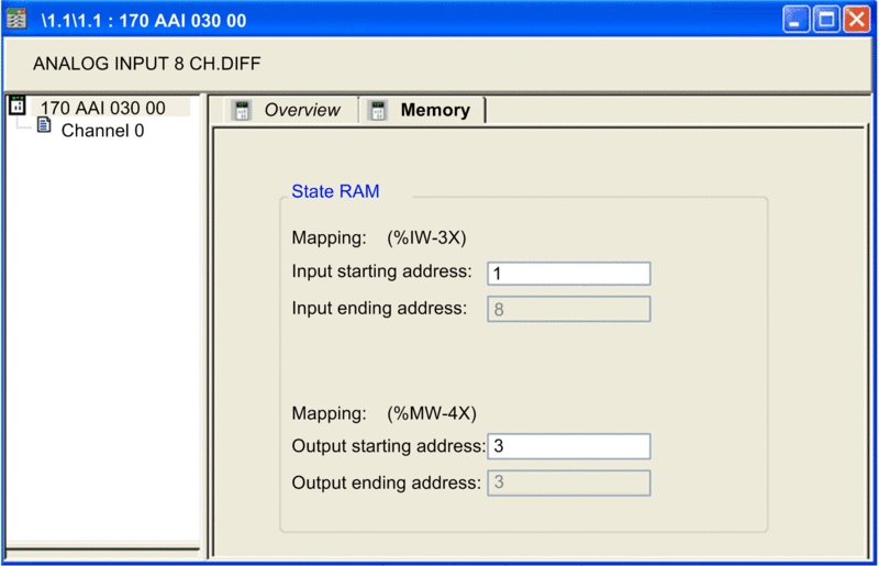
The State RAM area contains the following parameters:

Parameter

Description

Mapping

This parameter allows you to define the starting address for the inputs and outputs.

The following sizes of the memory areas are possible:

  • For inputs in Word format: %IW-3x

  • For outputs in Word format: %MW-4x

NOTE: State RAM addresses are not checked during input. If any range overlapping is detected or any address exceeds the range of the State RAM, an appropriate message is displayed during project validation or during the variable analyze process.