

Using the AEC Function Block
Use the AEC derived function block (DFB) to configure the 170 AEC 920 00 module in Control Expert program logic. Each counter channel requires a separate AEC DFB.
Each AEC DFB transmits many set values, one after another, which are then stored in the data structure par_arr, and returns the current values of the counters. The data transfer of bytes, words, and double words is started using a 0 -> 1 edge at the send input. All bits are sent in each scan cycle.
AEC DFB Structure
The AEC DFB presents the following structure:
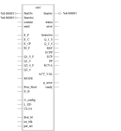
Inputs
Each AEC DFB presents the following outputs:
Parameters |
Data Type |
Meaning |
|---|---|---|
Start3x |
Word Arr 9 |
1. Address of the 8 input words |
Start4xi |
Word Arr 9 |
1. Address of the 8 output words |
Counter |
Byte |
Select counter 1 or 2 |
send |
BOOL |
0-1 Edge for the data transfer of byte, word, double word (BOOL values are sent in a cyclic manner) |
E_P |
BOOL |
Enable acceptance of preset value |
E_C |
BOOL |
Software Enable for counter |
E_CP |
BOOL |
Software Enable to freeze counter value |
EI_F |
BOOL |
Enable input filter |
Q1_3_F |
BOOL |
Activate forcing of digital outputs Q1/3 |
Q1_3 |
BOOL |
Record Valence of digital outputs Q1/3; |
Q2_4_F |
BOOL |
Activate forcing of digital outputs Q2/4; |
Q2_4 |
BOOL |
Record Valence of digital outputs Q2/4; |
Mode |
Byte |
4 bits for the choice of operation mode |
Pres_Mod |
Byte |
3 bits for the choice of preset mode |
D_B |
BOOL |
Invert counting direction; effective in all operating modes |
O_config |
Byte |
Configure outputs Q1/2 or Q3/4 |
L_ED |
BOOL |
Monitoring of the counter inputs A, B, Z for a line break. |
CLOA |
BOOL |
Behavior of Q1 to Q4 during bus interruption |
first_bl |
INT |
Number of the first data block to be sent |
tot_blk |
INT |
Total number of data blocks to be sent |
par_arr |
Word Arr 31 |
Data structure with 31 word data block: 1. word: Reference number 2. word: Set point value (High word) 3. word: Set point value (low word) |
Outputs
Each AEC DFB presents the following outputs:
Parameters |
Data Type |
Meaning |
|---|---|---|
Start4x |
Word Arr 9 |
1. Address of the 8 output words |
status |
Byte |
High-byte of 1st or 2nd input word (Status bits) |
error |
Byte |
Low-byte of 1st or 2nd input word (detected error bits) |
SratioNo |
Byte |
Reference number returned (if detected error = 1 F hex) |
Q_1_3 |
BOOL |
Valence of output Q1 or Q3 |
Q_2_4 |
BOOL |
Valence of output Q2 or Q4 |
REF |
BOOL |
Preset value has been accepted |
ECPP |
BOOL |
Freeze HW and SW counter values |
ECP |
BOOL |
Counter has been enabled |
PP |
BOOL |
Accept preset HW and SW values |
RCVA |
BOOL |
1. Count cycle is complete |
ACT_VAL |
DINT |
Current value or capture value |
p_error |
BOOL |
Detected transmission error (wrong value) |
ready |
BOOL |
Data transfer display: 0 = Transmission is active 1 = Transmission is complete |