|


|
Original instructions
|
|
|
Original instructions
|
 WARNING WARNING |
|
MODULE DESTRUCTION – LOSS OF APPLICATION
Failure to follow these instructions can result in death, serious injury, or equipment damage.
|
|
CPU
|
BMENOR2200H
|
|---|---|
|
BMEP582020
|
2
|
|
BMEP582040
|
3
|
|
BMEP584020
|
4
|
|
BMEP584040
|
4
|
|
BMEP586040
|
4
|
|
Backplane
|
Description
|
|---|---|
|
BMEXBP0400(H)
|
4-slot Ethernet backplane
|
|
BMEXBP0800(H)
|
8-slot Ethernet backplane
|
|
BMEXBP1200(H)
|
12-slot Ethernet backplane
|
|
BMEXBP0602(H)
|
6-slot (hardened) dual-PWS Ethernet backplane
|
|
BMEXBP1002(H)
|
10-slot (hardened) dual-PWS Ethernet backplane
|
|
Rack
|
Slot
|
Instruction
|
|---|---|---|
|
all racks
|
0, 1
|
Do not insert the BMENOR2200H module in these slots.
NOTE: These slots are reserved for the CPU module. |
|
BMEXBP1200(H)
|
2, 8, 10, 11
|
These X Bus-only slots do not support the Ethernet functionality of the dual-bus BMENOR2200H module.
|
|
BMEXBP1002(H)
|
2, 8
|
|
|
extended racks
|
—
|
You cannot install the dual-bus BMENOR2200H module in an extended rack.
NOTE: Extended racks do not have Ethernet ports. |
|
RIO drops
|
—
|
You cannot install the dual-bus BMENOR2200H module in an RIO drop.
|
|
NOTICE
|
|
UNINTENDED EQUIPMENT OPERATION
Failure to follow these instructions can result in equipment damage.
|
|
Step
|
Action
|
|---|---|
|
1
|
Set the rotary switch on the module to the Reset position.
|
|
2
|
Insert the module in the rack to power it up.
|
|
3
|
Remove the module from the rack to power it down.
|
|
4
|
Set the rotary switch on the module to the Secured or Standard position.
|
|
5
|
Reinsert the module in the rack to power it up.
|
|
Step
|
Action
|
|---|---|
|
1
|
Turn off the power supply to the rack.
|
|
2
|
Remove the protective cover from the module interface on the rack.
|
|
3
|
Configure the cyber security level for the module with the rotary switch according to the cyber security considerations (above).
|
|
4
|
Notice sub-steps a. and b. in the graphic:
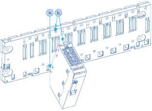 NOTE: Do not insert the BMENOR2200H module in slot 0 or 1 in the local rack. Those slots are reserved for the CPU. |
|
5
|
Tighten the retaining screw to hold the module in place on the rack:
 NOTE: Tightening torque: 0.4...1.5 N•m (0.30...1.10 lbf-ft). |
|
NOTICE
|
|
UNINTENDED EQUIPMENT OPERATION
Failure to follow these instructions can result in equipment damage.
|
|
Step
|
Action
|
|---|---|
|
1
|
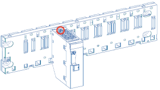
Remove the module from the rack by reversing the above steps for installing the module.
NOTE: Because this is a hot-swappable module, it is not necessary to power down the rack to remove the module. |
|
2
|
Set the rotary switch on the replacement module to the Reset position.
|
|
3
|
Insert the replacement module in the rack to power it up.
|
|
4
|
Remove the replacement module from the rack to power it down.
|
|
5
|
Set the rotary switch on the replacement module to the Secured or Standard position.
|
|
6
|
Reinsert the replacement module in the rack to power it up.
|
