|
Wiring and installation recommendations for the model TBX AES 400
|
|
|
(Original Document)
|
|
Precautions to take
|
||
|---|---|---|
|
Type of conductors
|
Use screened twisted pairs, with a minimum conductor cross-section of 0.28 mm2.
|
|
|
Cable screening
|
Connect the cable screening to the shortest TBX module ground on the TBX GND 015 grounding strip.
|
|
|
Arrangement of the conductors in cables
|
Multipair cables can be rearranged for signals of a similar type which have the same reference to ground.
|
|
|
Cable routing
|
Keep the measurement wires separate from the discrete I/O cables (in particular from relay outputs) and from power cables.
|
|
|
Sensor reference to ground
|
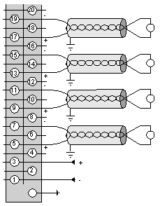
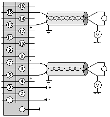
The TBX AES 400 has 4 inputs which are isolated from the PLC bus and from each other.
This double isolation means that sensors of different voltages can be used.
For safety reasons, a grounding network (15 MΩ//4.7 nF) is provided for each channel. This network causes a leakage current if the sensor is referenced to ground.
|
|
|
Sensor reference to ground (continued)
|
|
 |
|
Sensor reference to ground (continued)
|
|
 |
|
Specific cases Precautions to take
|
||
|---|---|---|
|
Thermocouple inputs
|
The thermocouple/terminal block connections must be carried out using compensation cables adapted to the type of thermocouple.
|
|
|
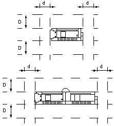
Preferential installations for thermocouple measurements are the following:
|
 |
|
|
||
|
Current inputs
|
When the input signal is a current of 0/20 mA or 4/2 0mA, it is necessary to connect a resistance of 250 Ω - 0.1 % - 1/2 Ω - 25 ppm / °C (TSX AAK2 : packs of 4 resistors) to terminals R+ and R- which are assigned to the channel.
|
|
|
Temperature probe inputs
|
2 or 4 wire temperature probes may be used.
For Pt100 2 wire probes, the probe can be at a distance of 2.50 m without affecting the measurement (1) if cables with a 2 mm2 cross-section are used.
For Pt1000/Ni1000 2 wire probes, the probe can be at a distance of 25 m without affecting the measurement (1) if cables with a 2 mm2 cross-section are used.
|
|
|
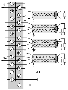
Note: the current source is common to all temperature probes which are then mounted in series.
The diagram opposite shows how the connecting terminals facilitate 4 wire wiring.
A fault in the wiring of the current source or in one of the temperature probes will lead to there being a fault on all the channels, which will be seen as a sensor connection fault.
|
Channels 0, 1 and 2: 4-wire Pt100 probe.
Channel 3: 2-wire Pt100 probe.
 |
|
|
Key:
|
||
|
(1)
|
Beyond this, the wire resistance systematically causes an error which can be corrected by the sensor alignment procedure.
|
|
 CAUTION CAUTION |
|
DEGRADATION OF PERFORMANCES
Any use which does not respect the thermocouple input recommendations (orientation, ambience, module power supply) will result in a degradation of performances of the TBX AES 400. However, in stable ambient temperature conditions, it is possible to reduce error by carrying out a sensor alignment.
Failure to follow these instructions can result in injury or equipment damage.
|