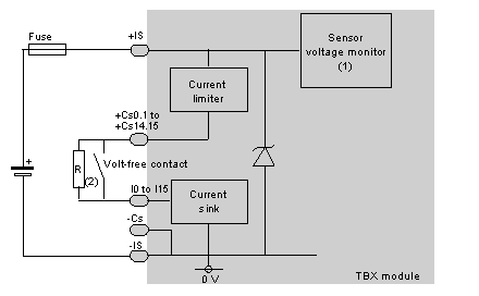
The following illustration shows the circuit diagram for a wiring check input.
1
Guaranteed threshold for monitored voltage OK: > 18 V, guaranteed threshold for monitored voltage faulty: < 14 V.
2
Resistance R for a dry contact or a 3-wire proximity sensor, enables the input wiring check to be used.
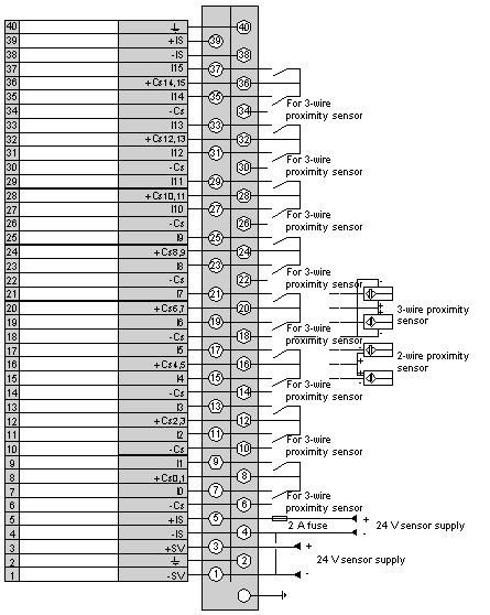
The following diagram illustrates the wiring of the terminal.
NOTE: a quick blow 2 A fuse, must be wired to the sensor power supply IS.
It is not necessary to connect
the two +IS terminals together, nor the two -IS terminals. The -SV terminal and a -IS (0 V) terminal must however be connected together.