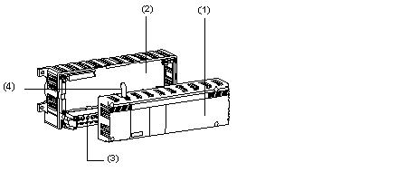
The modular modules are composed of a base unit and an optional extension. The extension is composed of the following elements:
-
A protective cover for the base unit (1),
-
A base unit (2) featuring Discrete and/or analog inputs and/or outputs.
-
A removable terminal block (3) for direct connection of the sensors and/or preactuators to the I/O. The necessary power supplies are also wired to the terminal block,
-
The following diagram shows the base unit of a modular TBX extension.
The TBXáCBSá010 assembly comprises:
-
A connection cable enabling the extension base unit to be connected to the communication module.
-
A cover, which is fixed to the extension base unit, protects the connector and gives the extension module (base unit + cover) a similar size and shape to that of the base module.
-
A self-adhesive label is used to label the channels 16 to 31.
To connect the extension module to the basic module, the connection cable between the 32-piná1/2áDIN connector on the communication module and the 32-piná1/2áDIN connector on the extension base unit is first connected, and then the cover is placed over this base unit and fixed in place.
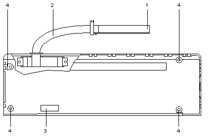
The following diagram shows a TBX cover/connection cable.
The following table describes the various elements of the TBX base unit.
|
Number
|
Description
|
|
1
|
32-pin male 1/2áDINácompound filled connector for linking the extension base unit to the communication module.
|
|
2
|
Flexible connection cable complete with connector 1 and a 32-pin male 1/2áDINáconnector for connection to the base unit.
|
|
3
|
Location for customer's Connection point address and Module number identification label.
|
|
4
|
4 screws for fixing cover to its base unit.
|

