|
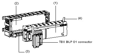
Modular TBX modules (IP20) : the base units
|
|
|
(Original Document)
|


|
Number
|
Description
|
|---|---|
|
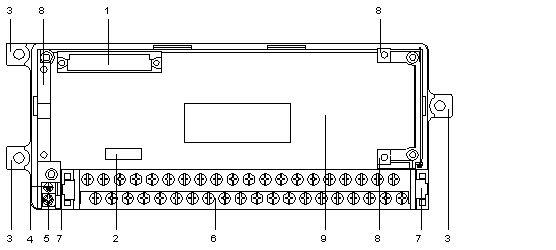
1
|
32-pin female 1/2 DIN connector for connection to the communication module.
|
|
2
|
Location for customer's Connection point address and Module number identification label.
|
|
3
|
Fixing lugs for the module.
|
|
4
|
Identification label indicating the type of base unit channels.
|
|
5
|
Screw clamp for grounding the unit.
|
|
6
|
Removable screw terminal block (with terminal block label) for wiring to sensors, preactuators and power supplies.
|
|
7
|
Extractors for removing the terminal block.
|
|
8
|
Tabs for fixing the communication module or cover.
|
|
9
|
Cover for access to electronic board for configuring the bases with input wiring check facilities.
|