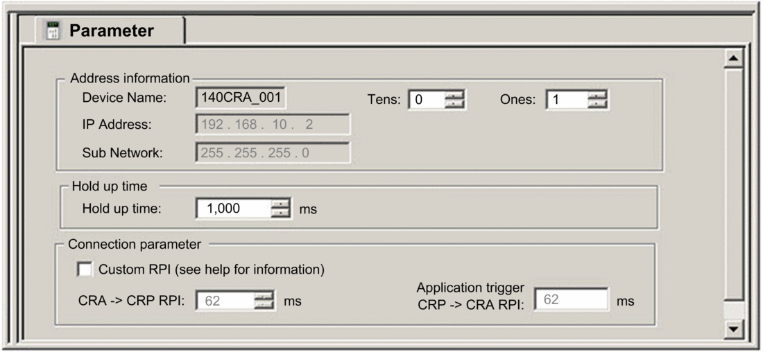
Parameter Tab (Remote I/O Drop)
This topic describes the Control Expert tab for an Ethernet remote I/O drop that includes a 140CRA31200 or BMXCRA312•0 adapter module.
Access the Parameter Tab
Access the Parameter tab in Control Expert:
Step |
Action |
Comment |
|---|---|---|
1 |
Expand (+) in the Control Expert . |
Path: /EIO Modicon X80 Drop |
2 |
Double-click the EIO drop (Quantum or Modicon X80. |
The EIO drop window appears. It contains the parameter tabs for the remote I/O drop. |
3 |
Select the tab. |
The tab appears:

Parameter Descriptions
Use the Control Expert tab to configure the following parameters for the Ethernet remote I/O drop.
parameters:
Parameter |
Comment |
|---|---|
|
The device name of the device includes a fixed device prefix and a number provided by the rotary switch. Valid device names conform to this structure:
Remember that xxx equals the
3-digit value selected on the rotary switches, so the device name
includes the device prefix ( When the device is placed on the Ethernet remote I/O drop, the number is set to the device number. The device number does not change when the device moves to a new location. Valid device numbers are unique within the application. A message like this appears when analysis reveals redundant device numbers:
NOTE: The device number
does not change if you move the drop, but you can modify the number.
However, if you modify the number, the link breaks between the device
name and the drop number. Schneider Electric recommends that you allow the drop number to equal the device name,
even if it can be modified.
|
|
You cannot edit the IP address and Sub network (mask) fields. The IP address is editable only in the IP Configuration tab of the 140CRP31200 module. The value for Sub network is deduced from the 140CRP31200 sub network mask. |
|
Hold up time parameter:
Parameter |
Comment |
|---|---|
|
The hold up time represents the time (ms) that device outputs are maintained in their current states after a communication disruption and before taking their fallback values:
|
The minimum holdup time differs for standalone and Hot Standby systems. If you assign a holdup time value that is less than the recommended minimum value, you can send an I/O module to the fallback state. When communications are restored, the I/O module restarts and may not operate as anticipated.
| WARNING | |
|---|---|
:
Parameter |
Comment |
|---|---|
|
Check this box to configure the CRA->CRP RPI value. NOTE: The minimum CRA->CRP RPI value is
5 ms.
|
|
Inputs: The RPI is the input refresh rate at which the adapter module sends inputs to the 140CRP31200 module. The RPI is set in the subscribe field for the adapter on the remote I/O drop.
You can configure this value when Custom RPI is checked. |
|
Outputs: Outputs are passed from the 140CRP31200 module to the adapter. Set the output refresh rate with the value () at the end of the CPU MAST task:
NOTE: The default value for the watchdog timer is
250 ms. If the MAST task does not finish within the watchdog period,
the process times out. If the watchdog is greater than 4 times the
MAST period, the drops could switch to fallback while the CPU is running. For example, MAST period = 20
ms, logic execution = 90 ms, watchdog time = 100 ms.
You cannot edit this value. All outputs are published synchronously or at the execution of the MAST task:
|
When the Periodic mode is selected for the MAST task, the Period value allows the complete execution of the logic. (The MAST can overrun when its execution time exceeds this value.) Valid values: 1...255 ms (increment: 1 ms).
When Cyclic mode is selected for the MAST task, the outputs are sent upon the completion of the task. The Watch Dog value (10 ... 1500 ms, default = 250) should be greater than the execution time. Valid values: 10...1500 ms (increment: 10 ms, default = 250 ms).


