|
Modules in a Quantum EIO System
|
|
|
Original instructions
|
|
Reference
|
Description
|
Picture
|
|---|---|---|
|
140CRP31200
|
Quantum Ethernet remote I/O head module
NOTE: In a Quantum local rack, insert only one 140CRP31200 module.
NOTE: A 140CRP31200 module is not considered a network option communication module.
|
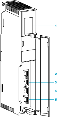 1LED display 2SERVICE port (ETH 1) 3INTERLINK port (ETH 2) 4DEVICE NETWORK port (ETH 3) 5DEVICE NETWORK port (ETH 4) |
|
140CRA31200
|
Quantum Ethernet remote I/O adapter module
NOTE: In each Quantum Ethernet remote I/O drop, insert only one 140CRA31200 module. |
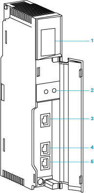 1LED display 2rotary switches 3SERVICE port (ETH 1) 4DEVICE NETWORK port (ETH 2) 5DEVICE NETWORK port (ETH 3) |
|
BMXCRA31200
|
Modicon X80 Ethernet remote I/O adapter module
NOTE: In each Modicon X80 remote I/O drop, insert only one BMXCRA31200 module. NOTE: This adapter module does not have a service port or a time stamping feature. It can be installed on an extended remote rack. NOTE: This adapter module only supports Modicon X80 analog and digital modules. |
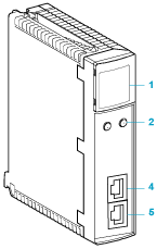 1LED display 2rotary switches 4device network port (ETH 2) 5device network port (ETH 3) |
|
BMXCRA31210
|
Modicon X80 Ethernet remote I/O adapter module
NOTE: In each Modicon X80 remote I/O drop, insert only one BMXCRA31200 module. NOTE: This adapter module has a service port (3) and a time stamping feature. It can be installed on an extended remote rack. |
 1LED display 2rotary switches 3service port (ETH 1) 4device network port (ETH 2) 5device network port (ETH 3) |
|
Reference
|
Description
|
Picture
|
|---|---|---|
|
140NOC78000
|
Quantum Ethernet distributed I/O head module
NOTE: In a Quantum local rack, you can install a maximum of five 140NOC78000 modules. |
 1LED display 2SERVICE port (ETH 1) 3INTERLINK port (ETH 2) 4DEVICE NETWORK port (ETH 3) 5DEVICE NETWORK port (ETH 4) |
|
140NOC78100
|
Quantum Ethernet control network head module
NOTE: In a Quantum local rack, insert only one 140NOC78100 module. |
 1LED display 2SERVICE/EXTEND port (ETH 1) 3INTERLINK port (ETH 2) 4CTRL NETWORK port (ETH 3) 5CTRL NETWORK port (ETH 4) |
|
140 NOE 771 ••
|
Quantum Ethernet communication module
NOTE: A Quantum local rack supports a maximum of 6 communication modules. While the 140 NOC 78• 00 head modules are designed specifically for a Quantum EIO system, you can use 140 NOE 771 •• modules and 140 NOM 2•2 00 modules to manage Ethernet distributed I/O and/or Modbus Plus systems. NOTE: Only a 140 NOE 771 •• module can be connected to a 140 CRP 312 00 head module on the local rack. Do not connect a 140 NOC 771 •• module with the 140 CRP 312 00 head module on the local rack. A 140 NOC 771 •• module is used to connect distributed I/O clouds that are not a physical part of the remote I/O network. NOTE: 140 NOC 771 •• modules are supported only in standalone systems; they are not supported in Hot Standby systems. |
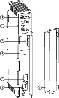 1module number 2LED display 3IP address writable area 4MAC address label 5100 base-FX cable connector 610/100 base-T RJ-45 cable connector 7removable door |
|
Quantum fiber converter module
NOTE: You can install 140 NRP 312 00/01 modules on the main ring and sub-rings for copper-to-fiber transitions. However, you cannot use these modules to connect sub-rings to the main ring. NOTE:
|
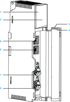 1model number, description code, color code 2LEDs 3removable door 4customer identification label (Fold label and place it inside the door.) 5Ethernet port 1 6Ethernet port 2 7fiber port 1 8fiber port 2 |
|
|
X80 fiber converter module
NOTE: You can install BMX NRP 0200/01 modules on the main ring and sub-rings for copper-to-fiber transitions. However, you cannot use these modules to connect sub-rings to the main ring. NOTE:
|
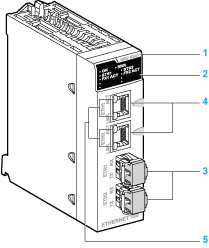 1model number 2LED display panel 3optical port with SFP transceiver for LC-type connector 4RJ45 Ethernet port 5LNK and ACT LED indicators on the RJ45 Ethernet port |
|
NOTICE
|
|
INOPERABLE EQUIPMENT
Failure to follow these instructions can result in equipment damage.
|
|
Part
|
ConneXium Switch
|
Ports
|
|---|---|---|
|
TCSESM083F23F1
|
8TX 1280
|
|
|
TCSESM063F2CU1
|
6TX/2FX-MM
|
|
|
TCSESM063F2CS1
|
6TX/2FX-SM
|
|
|
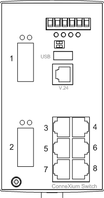
NOTE: These 3 switches use firmware version 6.0 or greater. NOTE: You can achieve up to 2 km with multi-mode fiber cables and up to 15 km with single-mode fiber cables in a Quantum EIO system. |
||
|
Switch
|
DRS Preconfiguration
|
|---|---|
|
TCSESM083F23F1
|
C1: RIOMainRing_RIOSubRing_DIOCloudsVx.xx.cfg
|
|
C2: RIOMainRing_DIOSubRing_DIOCloudsVx.xx.cfg
|
|
|
C7: Master_RIOMain_RIOSubRing_DIOCloudsVx.xx.cfg
|
|
|
C8: Slave_RIOMain_RIOSubRinig_DIOCloudsVx.xx.cfg
|
|
|
C9: Master_RIOMain_DIOSubRing_DIOCloudsVx.xx.cfg
|
|
|
C10: Slave_RIOMain_DIOSubRing_DIOCloudsVx.xx.cfg
|
|
|
TCSESM063F2CU1 or TSCESM063F2CS1
|
C3: RIOMainRingFx_RIOSubRingTx_DIOCloudsVx.xx.cfg
|
|
C4: RIOMainRingFx_DIOSubRingTx_DIOCloudsVx.xx.cfg
|
|
|
C5: RIOMainRingFxTx_RIOSubRingTx_DIOCloudsVx.xx.cfg
|
|
|
C6: RIOMainRingFxTx_DIOSubRingTx_DIOCloudsVx.xx.cfg
|
|
|
C11: Master_RIOMainFxTx_RIOSubRingTx_DIOCloudsVx.xx.cfg
|
|
|
C12: Slave_RIOMainFxTx_RIOSubRingTx_DIOCloudsVx.xx.cfg
|
|
|
C13: Master_RIOMainFxTx_DIOSubRingTx_DIOCloudsVx.xx.cfg
|
|
|
C14: Slave_RIOMainFxTx_DIOSubRingTx_DIOCloudsVx.xx.cfg
|
|
|
C15: CRPLinkHotStandbyLDVx.xx.cfg
|