|
Creating a Project in Control Expert
|
|
|
Original instructions
|
|
Step
|
Action
|
|---|---|
|
1
|
Open Control Expert.
|
|
2
|
In the Control Expert main menu, select File → New....
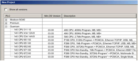
The New Project window opens displaying a list of Schneider Electric controller types.
|
|
3
|
In the New Project window, expand the Quantum node and select a CPU. In this example, select the 140 CPU 651 60 controller:
 |
|
4
|
Click OK. Control Expert displays the Project Browser, below.
 |
|
5
|
To save the project, select File → Save. The Save As dialog opens.
|
|
6
|
In the Save As dialog, type in a File name — which will be the name of your Control Expert project — then click Save. Control Expert saves your project to the specified path location.
NOTE: You can change the default location Control Expert uses to store project files. Before saving your project:
1
Select Tools → Options. The Options Management window opens.
2
In the left pane, navigate to Options → General → Paths.
3
In the right pane, type in a new path location for the Project path. You can also edit the:
|
|
Step
|
Action
|
|---|---|
|
7
|
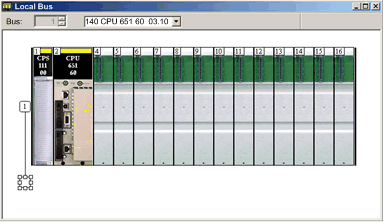
In the Project Browser, double click Local Bus. Control Expert displays both the:
|
|
8
|
In the Hardware catalog, under the Supply node, use your mouse to select then drag a 140 CPS 111 00 power supply to a position in the rack — in this example, slot 1.
 |
|
9
|
In the File menu, select Save, to save your edits.
NOTE: Schneider Electric recommends that you periodically save your changes as you make edits. |
|
Step
|
Action
|
|---|---|
|
10
|
Returning to the Hardware catalog, under the Communication node, use your mouse to select then drag a 140NOC78000 control head module to an open slot in the rack — in this example, slot 5.
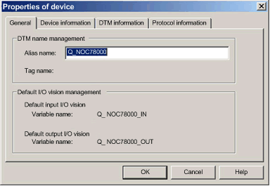
When you drop the module into the rack, Control Expert opens the communication module Properties window.
|
|
11
|
In the General tab of the module properties window, Control Expert assigns a the device an alias name, in this example, Q_NOC78000. You can type in a name to change the default alias name.
 When you change the alias name, Control Expert changes the base input and output type and variable names to match the edited alias name.
NOTE:
|
|
12
|
In the File menu, select Save to save your edits.
|
|
13
|
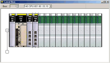
Click OK to close the Properties window. The Local Bus now displays the modules you have added:
 |
|
14
|
|
|
15
|
Open the DTM Browser in Control Expert to configure the DTM properties of the 140NOC78000 module by clicking Tools → DTM Browser.
 |