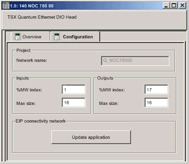
Use the Configuration tab of the 140NOC78000 distributed I/O head module’s Properties window to configure the:
The following steps present one example of how to configure the size and location of inputs and outputs. Your own project configuration may differ.
Setting Input and Output Memory Addresses and Naming the Module
The Properties window opens when you double-click the left mouse button on the image of the 140NOC78000 module in either the Local Bus window or the Project Browser.
When you select the Configuration tab, it displays the network, or Alias, name. This is the name assigned to the network channel when you added the 140NOC78000 module to the project.
Use the Configuration page to edit the communication module inputs and outputs, as follows:
To input the above settings, perform the following steps:
|
Step
|
Action
|
|
1
|
In the module’s Properties window, select the Configuration tab.
|
|
2
|
Type in the size and starting position of the inputs and outputs, as follows:
|
|
In the Inputs area:
-
In the %MW index field, type in a starting address for inputs, in this example: 1.
-
In the Max size field, type in the maximum number of 16-bit words dedicated to inputs, in this example:16.
|
|
In the Outputs area:
-
In the %MW index field, type in a starting address for outputs, in this example: 17.
-
In the Max size field, type in the maximum number of 16-bit words dedicated to outputs, in this example: 16.
|
|
Notes:
-
The inputs and outputs can be located at any available address and do not need to be located in adjacent areas. Confirm that the space allocated to inputs and outputs does not overlap.
-
Control Expert automatically reserves space for two arrays of 32 bytes, as follows:
-
for connection health bits, located at the beginning of the space configured for inputs
-
for connection control bits, located at the beginning of the space configured for outputs
-
The specified %MW range for both inputs and outputs are available in the CPU. For more information, refer to the Processor Configuration Screen topic in the Control Expert help file.
|
|
3
|
In Control Expert select Edit → Validate (or click the Validate  toolbar button) to save the address and size settings for inputs and outputs.
NOTE: After you validate module settings for the first time, you cannot edit the module name. If you subsequently decide to change the module name, delete the existing module from the configuration, then add and rename a replacement module.
|
Completing the Ethernet Network Configuration
After configuring settings for inputs and outputs, the next step is to configure the 140NOC78000 module settings, beginning with its
Channel Properties, and then configure remote Ethernet network devices.
NOTE: After you input configuration settings for the 140NOC78000 module and remote devices, return to the
Configuration tab of the 140NOC78000 module’s
Properties window and click the
Update application button. This
creates derived data type (DDT) variables that display the following information and commands for your Control Expert project:
-
connection health bits, that display the status of each connection
-
connection control bits, you can use to toggle each connection on and off
-
the value of input and output items
-
module and device configuration settings
-
free memory space that has been reserved, but not yet allocated

 toolbar button) to save the address and size settings for inputs and outputs.