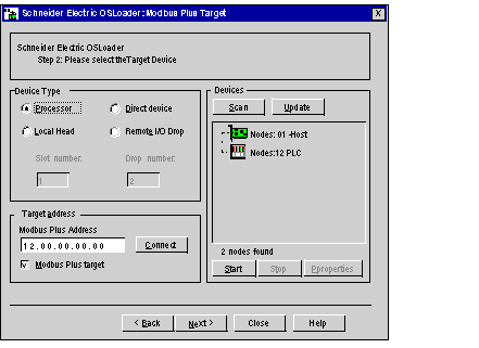
The Modbus Plus Target dialog box allows you to choose the target device according to the Modbus Plus communication type.
The main elements of the Modbus Plus Target screen are described in the following paragraphs.
The device types
supported by OSLoader and available for the Modbus Plus communication type are displayed in the
Device Type area. Check the box corresponding to the device desired.
The Slot number and Drop number boxes may be enabled or disabled according to the device type selected.
The following table shows the four possible cases.
|
Device Type Selected
|
Slot Number
|
Drop Number
|
|
Processor
|
Disabled
|
Disabled
|
|
Local Head
|
Enabled
|
Disabled
|
|
Remote I/O Drop
|
Enabled
|
Enabled
|
|
Direct device
|
Disabled
|
Disabled
|
The following elements are displayed in the Target Address area.
|
Fields
|
Description
|
|
Modbus Plus Address
|
In this field, you must enter the address of the target device specific to the Modbus Plus communication type.
|
|
Modbus Plus Target
|
Activate the checkbox IF the device is finally reached by a Modbus Plus communication port.
|
|
Connect
|
Press this button to connect OsLoader to the target device whose address is specified in the Modbus Address Plus entry field.
If the connection is established, the target device is added to the directory tree in the Devices area.
|
The directory tree in the Devices area displays the list of connected devices. At OSLoader startup, when no connection is enabled, the directory tree is empty.
The following table shows the list of icons used in the directory tree and the corresponding description.
|
Icon
|
Description
|
|
|
Processor in stop mode (Stop)
|
|
|
Processor in run mode (Run)
|
|
|
Processor is not configured (no application was ever loaded into the PLC)
|
|
|
Host adapter (SA85 or PCMCIA Modbus Plus card)
|
|
|
Bridge or Bridge plus or Bridge mux
|
|
|
Input/output port
|
|
|
Remote input/output module
|
|
|
Device unknown
|
When you click on a specific device, the Modbus Plus address entry field of the Target Address area is automatically updated.
Proceed to the Device Properties dialog box by double-clicking on a specific device.
Press the Scan button to launch a sniffing program on the network. When a device is detected, its name and address are added to the directory tree in the Devices area. If a bridge is detected, the devices behind are added as sub-branches in the same directory tree.
Press the Update button to update the on/off status of the processors contained in the directory tree.
The Start and Stop buttons are only available if a processor in the directory tree of the Devices field is selected. In other cases, they are disabled.
Stop the processor by pressing the Stop button.
Restart the processor by pressing the Start button.
NOTE: For safety PLCs (Control Expert XLS) the Start/Stop PLC functions are password protected. If you try to start or stop the processor a dialog box is displayed and you are asked to enter the password.
The
Device Properties dialog
box, which is accessible by pressing the
Properties button in the
Devices area, gives access to information concerning the device selected.


