|


|
Original instructions
|
|
|
Original instructions
|
|
Input/Output
|
Description
|
|---|---|
|
Drive_Ready&Emergency input (optional)
|
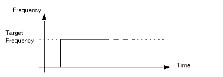
The pulse output is generated as long as a current goes through Drive_Ready&Emergency input.
|
|
Proximity&LimitSwitch input (optional)
|
Used as a LimitSwitch.
|
|
Drive_Enable output
|
To be connected to the corresponding input of the drive.
Enables the drive when active.
This output is directly controlled through an implicit command object (%Qr.m.c.0).
|
|
Parameter
|
Valid Values
|
|---|---|
|
PTO Output Mode
|
Value 0: Pulse + Direction (Default)
Value 1: CW/CCW
Value 2: A/B Phases
Value 3: Pulse + Direction – Reverse
Value 4: CW/CCW – Reverse
Value 5: A/B Phases – Reverse
|
 WARNING WARNING |
|
UNINTENDED APPLICATION BEHAVIOR-COMMAND SENT ON EACH PLC CYCLE
Commands will be sent on every PLC cycle if EN is set to 1.
Failure to follow these instructions can result in death, serious injury, or equipment damage.
|
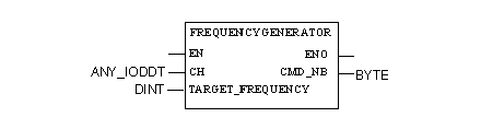
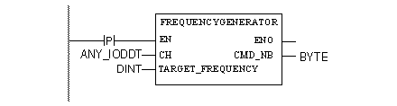
FREQUENCYGENERATOR (CH := (*ANY_IODDT*), TARGET_FREQUENCY := (*DINT*))
ST (*BYTE*)
(*BYTE*) := FREQUENCYGENERATOR (CH := (*ANY_IODDT*), TARGET_FREQUENCY := (*DINT*));
if (ChangeFreq = True) then %CH0.1.0.CMD_CODE := 1; %CH0.1.0.TGT_VELOCITY := 5000; WRITE_CMD(%CH0.1.0); ChangeFreq := False; end_if;
|
Parameter
|
Valid Values
|
|---|---|
|
Target Velocity (in Hz)
|
-200 kHz to 200 kHz
Absolute value limited by Max Frequency
|
|
Explicit Command Parameters
|
Setting Parameters
|
Adjustment Parameters
|
|||
|---|---|---|---|---|---|
|
Address
|
Parameter
|
Address
|
Parameter
|
Address
|
Parameter
|
|
%MWr.m.c.6 (byte 0)
|
Command Code (=1)
|
%KWr.m.c.1(byte 0)
|
Output Mode
|
%MWr.m.c.25
|
Hysteresis
|
|
%MDr.m.c.10
|
Target Frequency
|
%KDr.m.c.6
|
Max Frequency
|
|
|
