CFG_CP_V: CamProfile with Variable Master Increments
(Original Document)
Function Description
This function block configures a CamProfile with variable master increments.
Additional parameters EN and ENO may be configured.
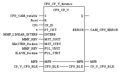
Representation in FBD
Representation:
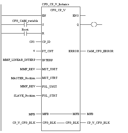
Representation in LD
Representation:
Representation in IL
Representation:
CAL CFG_CP_V_Instance (S:=CFG_CAM_variable, R:=Reset,
    CP_ID:=CP3, PT_CNT:=4, INTERP:=MMF_LINEAR_INTERP,
    MST_UNIT:=MMF_REV, MST_STRT:=MASTER_Position,
    FOL_UNIT:=MMF_REV, FOL_STRT:=SLAVE_Position, MFB:=MFB,
    CFG_BLK:=CP_V_CFG_BLK, ERROR=>CAM_CFG_ERROR)
Representation in ST
Representation
CFG_CP_V_Instance (S:=CFG_CAM_variable, R:=Reset,
    CP_ID:=CP3, PT_CNT:=4, INTERP:=MMF_LINEAR_INTERP,
    MST_UNIT:=MMF_REV, MST_STRT:=MASTER_Position,
    FOL_UNIT:=MMF_REV, FOL_STRT:=SLAVE_Position, MFB:=MFB,
    CFG_BLK:=CP_V_CFG_BLK, ERROR=>CAM_CFG_ERROR) ;
Parameter Description
Description of input parameters:
Parameter
Data Type
Meaning
S
Rising input starts configuration of the CamProfile.
R
BOOL
Resets block and prevents configuration. It halts configuration at the end of the current step.
CP_ID
Axis ID for CamProfile to be configured.
PT_CNT
INT
The number of points in the CamProfile.
INTERP
Interpolation type: linear or cubic.
MST_UNIT
UDINT
Position units of the master.
MST_STRT
Array of the master position data (n must be ≥ PT_CNT).
FOL_UNIT
UDINT
Position units of the slave.
FOL_STRT
ARRAY [1 .. n] OF REAL
Array of the slave position data (n must be ≥ PT_CNT).
Description of in-output parameters:
Parameter
Data Type
Meaning
MFB
Must be connected to the MMFStart block of 200 registers.
CFG_BLK
Data block where the CamProfile configuration data will be stored.
Description of output parameters:
Parameter
Data Type
Meaning
Q
BOOL
True when the configuration has completed (reset by R).
ERROR
INT
First error code that is generated during configuration.
Example
When input CFG_CAM_variable turns on, a variable master increment CamProfile, identified as CamProfile 3 (CP3), is created in the motion controller, the velocity units for both the master and follower are set to revolutions on the input pins MST_UNIT and FOL_UNIT. The interpolation type is configured as LINEAR on the INTERP input pin. The master follows the variable point paths that are defined in register block MASTER_Position and specified on input pin MST_STRT. The follower path positions are defined in register block SLAVE_Position and specified on input pin FOL_STRT. Both the master and follower variable positions must be determined and entered into the specified PLC registers.
Master and Follower Positions
The master and follower positions that are entered into the PLC registers are listed in the following table:
Point Number
Master 409500
Follower 409600
1
0.0
0.0
2
0.2
0.5
3
0.6
0.5
4
0.8
0.0
During this profile execution, both the master and follower will start at position 0. When the master reaches +0.2 revolutions, the follower reaches +0.5 revolutions. While the master is moving from +0.2 through +0.6 revolutions, the follower remains at +0.5 revolutions. When the master reaches 0.8 revolutions, the follower moves back to 0 revolutions. While the master is moving from +0.8 revolutions to 0 revolutions, the follower remains at 0 revolutions.
Runtime Errors
If an error occurs during the configuration of this CamProfile, the error number can be examined at CAM_CFG_ERROR. This CamProfile configuration information is located in the register block CP_V_CFG_BLK after successful completion of the configuration.
NOTE: For a list of all error codes and values of the block, refer to Tables of Error Codes for the Motion Library.