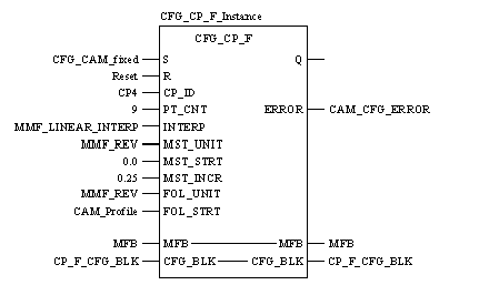
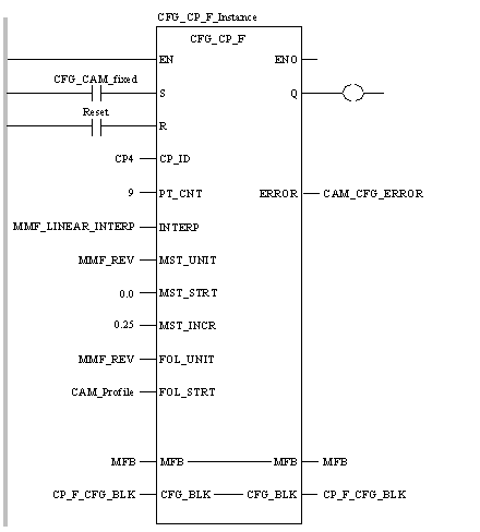
|
|
(Original Document)
|


CAL CFG_CP_F_Instance (S:=CFG_CAM_fixed, R:=Reset,
    CP_ID:=CP4, PT_CNT:=9, INTERP:=MMF_LINEAR_INTERP,
    MST_UNIT:=MMF_REV, MST_STRT:=0.0, MST_INCR:=0.25,
    FOL_UNIT:=MMF_REV, FOL_STRT:=CAM_Profile, MFB:=MFB,
    CFG_BLK:=CP_F_CFG_BLK, ERROR=>CAM_CFG_ERROR)
CFG_CP_F_Instance (S:=CFG_CAM_fixed, R:=Reset,
    CP_ID:=CP4, PT_CNT:=9, INTERP:=MMF_LINEAR_INTERP,
    MST_UNIT:=MMF_REV, MST_STRT:=0.0, MST_INCR:=0.25,
    FOL_UNIT:=MMF_REV, FOL_STRT:=CAM_Profile, MFB:=MFB,
    CFG_BLK:=CP_F_CFG_BLK, ERROR=>CAM_CFG_ERROR) ;
|
Parameter
|
Data Type
|
Meaning
|
|---|---|---|
|
S
|
Rising input starts configuration of the CamProfile.
|
|
|
R
|
BOOL
|
Resets block and prevents configuration. It halts configuration at the end of the current step.
|
|
CP_ID
|
Axis ID for the CamProfile ID to be configured.
|
|
|
PT_CNT
|
INT
|
The number of points in the CamProfile.
|
|
INTERP
|
Interpolation type: linear or cubic.
|
|
|
MST_UNIT
|
UDINT
|
Position units of the master.
|
|
MST_STRT
|
Master position data.
|
|
|
MST_INCR
|
Fixed master position increment.
|
|
|
FOL_UNIT
|
UDINT
|
Position units of the follower.
|
|
FOL_STRT
|
ARRAY [1 .. n] OF REAL
|
Array where the CamProfile configuration information will be stored.
|
|
Parameter
|
Data Type
|
Meaning
|
|---|---|---|
|
MFB
|
Must be connected to the MMFStart block of 200 registers.
|
|
|
CFG_BLK
|
Data block where the CamProfile configuration data will be stored.
|
|
Parameter
|
Data Type
|
Meaning
|
|---|---|---|
|
Q
|
BOOL
|
True when the configuration has completed (reset by R).
|
|
ERROR
|
INT
|
First error code that is generated during configuration.
|
|
Path Point
|
Follower Position Point
|
|---|---|
|
CAM_Profile[0]
|
0.0
|
|
CAM_Profile[1]
|
0.25
|
|
CAM_Profile[2]
|
0.5
|
|
CAM_Profile[3]
|
0.75
|
|
CAM_Profile[4]
|
1.0
|
|
CAM_Profile[5]
|
0.75
|
|
CAM_Profile[6]
|
0.5
|
|
CAM_Profile[7]
|
0.25
|
|
CAM_Profile[8]
|
0.0
|
