CFG_FS: FollowerSet
(Original Document)
Function Description
This function block configures a FollowerSet.
Additional parameters EN and ENO may be configured.
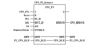
Representation in FBD
Representation:
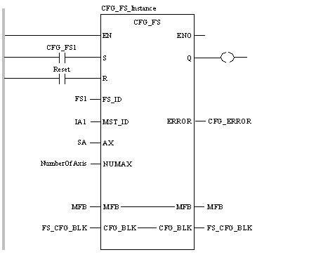
Representation in LD
Representation:
Representation in IL
Representation:
CAL CFG_FS_Instance (S:=CFG_FS1, R:=Reset, FS_ID:=FS1,
    MST_ID:=IA1, AX:=SA, NUMAX:=NumberOfAxis, MFB:=MFB,
    CFG_BLK:=FS_CFG_BLK, ERROR=>CFG_ERROR)
Representation in ST
Representation
CFG_FS_Instance (S:=CFG_FS1, R:=Reset, FS_ID:=FS1,
    MST_ID:=IA1, AX:=SA, NUMAX:=NumberOfAxis, MFB:=MFB,
    CFG_BLK:=FS_CFG_BLK, ERROR=>CFG_ERROR) ;
Parameter Description
Description of input parameters:
Parameter
Data Type
Meaning
S
Rising input starts configuration.
R
BOOL
Resets block and prevents configuration. It halts configuration at the end of the current step.
FS_ID
Axis ID for the FollowerSet to be configured.
MST_ID
INT
Axis ID for the master axis.
AX
Axis ID for single axis member to be included in the set.
NUMAX
Number of Axis. Range from 2 to 8.
Description of in-output parameters:
Parameter
Data Type
Meaning
MFB
Must be connected to the MMFStart block of 200 registers.
CFG_BLK
Data block where the FollowerSet data will be stored.
Description of output parameters:
Parameter
Data Type
Meaning
Q
BOOL
True when the configuration has completed (reset by R).
ERROR
INT
First error code that is generated during configuration.
Example
When CFG_FS1 turns on, the configuration of FS1 occurs. During the creation of FS1, IA1 is assigned as the master at input pin MST_ID, and axes SA is assigned at input pin AX as member of this set. The number of pins ranges from 2 to 8 and the user must give the appropriate value on the NUMAX pin. If the user gives a value out of bounds, the input is forced to either the max. or min. value according to which boundary is exceeded. The FollowerSet information, including the member axes, are moved into the PLC register block FS_CFG_BLK that is assigned at output pin CFG_BLK. For detailed information on the size and layout of this register data block, refer to the FSCfg Data Structure. The default follower configuration for the member axes is MMF_CONTROLLER_GEAR_FEEDBACK with a gear ratio of 1:1. If the feedback configuration requirements are not the default, use the MMF_SUB block to modify the configuration for that member axis.
Runtime Errors
For a list of all error codes and values of the block, refer to Tables of Error Codes for the Motion Library.