|
|
(Original Document)
|


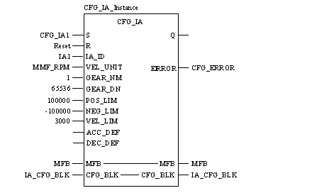
CAL CFG_IA_Instance (S:=CFG_IA1, R:=Reset, IA_ID:=IA1,
    VEL_UNIT:=MMF_RPM, GEAR_NM:=1, GEAR_DN:=65536,
    POS_LIM:=100000, NEG_LIM:=-100000, VEL_LIM:=3000,
    MFB:=MFB, CFG_BLK:=IA_CFG_BLK, ERROR=>CFG_ERROR)
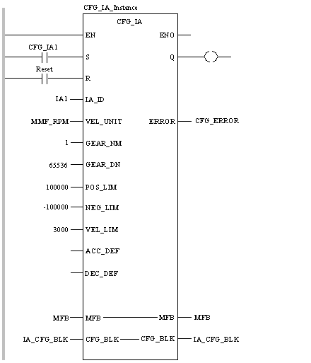
CFG_IA_Instance (S:=CFG_IA1, R:=Reset, IA_ID:=IA1,
    VEL_UNIT:=MMF_RPM, GEAR_NM:=1, GEAR_DN:=65536,
    POS_LIM:=100000, NEG_LIM:=-100000, VEL_LIM:=3000,
    MFB:=MFB, CFG_BLK:=IA_CFG_BLK, ERROR=>CFG_ERROR) ;
|
Parameter
|
Data Type
|
Meaning
|
|---|---|---|
|
S
|
Rising input starts configuration.
|
|
|
R
|
BOOL
|
Resets block and prevents configuration. It halts configuration at the end of the current step.
|
|
IA_ID
|
Axis ID for ImaginaryAxis to be configured.
|
|
|
VEL_UNIT
|
Velocity units for this axis.
|
|
|
GEAR_NM
|
Number of axis units.
|
|
|
GEAR_DN
|
REAL
|
Number of drive units.
|
|
POS_LIM
|
REAL
|
Positive position limit (this is optional).
|
|
NEG_LIM
|
REAL
|
Negative position limit (this is optional).
|
|
VEL_LIM
|
REAL
|
Velocity limit (this is optional).
|
|
ACC_DEF
|
REAL
|
Default acceleration (this is optional).
|
|
DEC_DEF
|
REAL
|
Default deceleration (this is optional).
|
|
Parameter
|
Data Type
|
Meaning
|
|---|---|---|
|
MFB
|
Must be connected to the MMFStart block of 200 registers.
|
|
|
CFG_BLK
|
Data block where the ImaginaryAxis configuration data will be stored.
|
|
Parameter
|
Data Type
|
Meaning
|
|---|---|---|
|
Q
|
BOOL
|
True when the configuration has completed (reset by R).
|
|
ERROR
|
INT
|
First error code that is generated during configuration.
|
