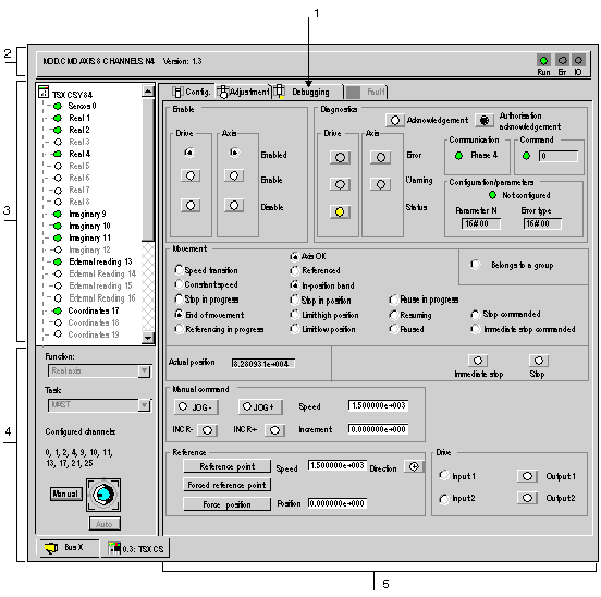
The different debug screens can be used, for all types of channels, to display the state of the inputs and outputs of a module channel as well as any faults.
It also enables you to command language objects (set to 1 or 0, forcing/unforcing a bit, etc.).
These parameters are accessible in online mode.
It also gives access to the configuration and adjustment screens.
NOTE: For an introduction to the processes of configuring, adjusting and debugging a project, see the section on Common application specific functions.
The following figure shows an example of a debug screen for the TSX CSY 84 module (the debug screen for the TSX CSY 164 module is identical):
The table below shows the different elements of the debug screen.
|
Address
|
Element
|
Function
|
|
1
|
Tabs
|
The tab in the foreground indicates the current mode (Debug in this example). Each mode can be selected using the corresponding tab. Available modes are:
-
Debug, accessible only in online mode,
-
Diagnostic (Fault), accessible only in online mode,
-
Adjustment,
-
Configuration.
|
|
2
|
Module zone
|
Displays the short title of the module.
In the same zone there are 3 lamps showing the status of the module in online mode:
-
RUN shows the operating mode for the module.
-
ERR indicates an internal module error.
-
I/O indicates a fault outside the module or an application fault.
|
|
3
|
Channel zone
|
Allows you to:
-
by clicking on the device reference, displays the tabs:
-
chooses the channel,
-
display the Symbol, channel name defined by the user (via the variables editor).
|
|
4
|
General parameters zone
|
Used to force bits and view the counting function:
-
Unforce: button used to unforce forced bits.
-
Function: recalls the configured counting function. This information cannot be modified.
-
Task: displays the MAST or FAST task configured. This information cannot be modified.
|
|
5
|
Current parameters zone
|
This zone displays the state of the inputs, outputs and different parameters of the counting in progress. If the contents of the counting register are unusable following an input fault, the message or LED Invalid measure displays red.
|
