|
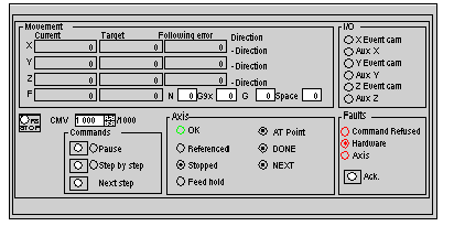
Automatic Mode (Auto)
|
|
|
(Original Document)
|

|
Display zone
|
Description
|
|---|---|
|
Current X, Y, Z
|
Displays the current position of the moving part on the X, Y and Z axes respectively. This value is expressed in measurement units defined in the configuration
|
|
Target X, Y, Z
|
Displays the setpoint position (reach position) on the X, Y and Z axes respectively
|
|
F Current
|
Displays the current moving part speed using the measurement unit defined in configuration.
|
|
F Target
|
Displays the moving part setpoint speed (speed to be attained)
|
|
Following error X, Y, Z
|
Displays the deviation between the calculated setpoint position and the real position of the moving part (the following error) on the X, Y and Z axes respectively
|
|
N
|
Indicates the step number for the instruction which is in progress
|
|
G9x
|
Indicates the movement type for the instruction which is in progress
|
|
G
|
Indicates the instruction code which is in progress
|
|
Space
|
Indicates the space where the movement in progress is being carried out (0 = XY, 1 = XZ, 2 = YZ, 3 = XYZ)
|
|
Direction X, Y,
|
+ Direction: indicates the part is moving in a positive direction on the X, Y and Z axes respectively
- Direction: indicates the part is moving in a negative direction on the X, Y and Z axes respectively
|
|
Command
|
Description
|
|---|---|
|
STOP F8
|
Stops the moving part on all interpolated axes
|
|
CMV
|
Used to enter a value from 0 to 2000 which determines the speed multiplier coefficient (0.000 to 2000 in intervals of 1/1000)
|
|
Command
|
Description
|
|---|---|
|
Pause
|
Commands the moving part to stop at the end of a movement with a stop in progress
|
|
Step by step
|
Changes the axis to step by step mode
|
|
Next step
|
Step by step mode activates the waiting movement
|
|
LED
|
State
|
Indication
|
|---|---|---|
|
OK
|
Lit
|
All axes are in operating state
|
|
Referenced
|
Lit
|
All axes are referenced
|
|
Stopped
|
Lit
|
All axes are at a stop (moving part stationary)
|
|
Feed hold
|
Lit
|
Axis movement is suspended (Feed hold)
|
|
AT Point
|
Lit
|
The movement in progress is finished and the moving part is in the target window
|
|
DONE
|
Lit
|
The movement(s) in progress is (are) finished
|
|
NEXT
|
Lit
|
The following movement command can be sent to the module
|
|
LED
|
Indication
|
|---|---|
|
X, Y or Z Came Evt
|
State of signal (0 or 1) on Event input for X, Y or Z axes
|
|
Aux X, Y or Z
|
State of signal (0 or 1) on auxiliary input for X, Y or Z axes
|
|
LED / Button
|
State
|
Indication
|
|---|---|---|
|
Command Refused
|
Lit
|
The last XMOVE received has been refused
|
|
Hardware
|
Lit
|
External hardware error on one of the interpolated axes
|
|
Axis
|
Lit
|
Application fault on one of the interpolated axes
|
|
Ack.
|
/
|
Fault acknowledgment button. Activating this button acknowledges all faults which have disappeared
|