The following parameters must be entered for programming an interpolated movement function:
XMOVE (AXIS_CH3,N_Run,G9_,G,SPACE,X,Y,Z,F,M)
AXIS_CH3 is an IODDT type variable corresponding to channel 3 of the axis control module on which the function must apply. AXIS_CH3 is of type T_INTERPO_STD
N_Run defines the movement number (between 0 and 32767). This number identifies the movement effected by the XMOVE function.
In debugging mode, this number is used to recognize the current movement.
G9_ defines the movement type:
|
Code
|
Movement type
|
|
90
|
Movement to an absolute position.
|
|
91
|
Movement to a relative position with respect to the current position.
|
|
98
|
Movement to a relative position with respect to the stored position PREF1
|
To choose the movement type, use the scroll button on the right of the G9_ field, or enter the code directly with a "direct entry" (without going via the Details screen).
SPACE defines the plane or space number where the movement must take place. This parameter specifies the list of axes affected by the movement :
|
Code
|
Meaning
|
|
0
|
Movement in the XY plane.
|
|
1
|
Movement in the XZ plane.
|
|
2
|
Movement in the YZ plane.
|
|
3
|
Movement in the XYZ space.
|
NOTE: When the group of interpolated axes is in 2-D, the SPACE field must be at 0. The Z field for the XMOVE function becomes not significant and is disregarded.
Co-ordinates for Position to Reach
X, Y, Z defines the coordinates for reach position for channels 0, 1 and 2, or for the position which the moving part is heading for (in the case of a non-stop movement). This position can be:
This value is expressed as a unit defined by the Length units configuration parameter for each axis.
Moving Part Movement Speed
F defines the speed of the moving object (or the movement speed required for the direction of movement to be carried out). This speed can be:
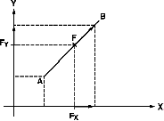
Example for a 2 axis system:
Using speed F, the interpolator calculates FX and FY projections which are used to guide the 2 axes on their trajectory.
The actual movement speed is equal to required speed F multiplied by the SMC speed modulation coefficient, whose value can be adjusted in the interval [0.001, 2.000].
M defines a word which codes nibbles (in hexadecimal):
M Parameter :
NOTE: Coding is automatically completed in the M field on the Details screen, when the choices have been made using the check-boxes and buttons offered by the screen.

