|
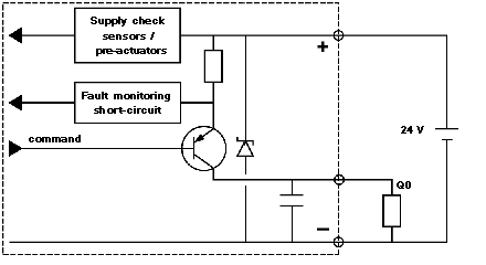
Characteristics of the Q0 Reflex Outputs
|
|
|
(Original Document)
|

|
Electrical characteristics
|
Value
|
Units
|
|---|---|---|
|
Nominal voltage
|
24
|
V
|
|
Voltage limits
max for 1 hour in 24 hours (Utime)*
|
19 to 30
34
|
V
V
|
|
Nominal current
|
500
|
mA
|
|
Max voltage fall "On"
|
< 1
|
V
|
|
Leakage current
|
< 0,3
|
mA
|
|
Max current to 30 V and to 34 V
|
625
|
mA
|
|
Communication time
|
< 500
|
μs
|
|
Dielectric rigidity with the ground connection
|
1500 Veff 50/60 Hz per min
|
|
|
Compatibility with direct current inputs
|
All positive logic inputs whose input resistance is less than 15 kΩ
|
|
|
IEC 1131 compatibility
|
Yes
|
|
|
Monitoring short-circuits of each channel
|
One signaling bit per channel
|
|
|
Reset
|
One bit per channel in write mode via program
|
|
|
Protection against overloads and short-circuits
|
Using current limiter and thermal circuit breaker (0.7A< id < 2 A)
|
|
|
Protection against overvoltage of the channels
|
Zener (breakdown) between outputs and +24V
|
|
|
Protection against polarity inversions
|
Using a reverse diode on the supply
|
|
|
Power of a lamp with filament
|
10 W (max)
|
|