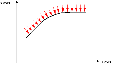
This type of interpolation enables use of a third axis that will automatically follow the curve created using two axes.
This third axis will allow a cutting tool to be positioned in cases where an angle of approach has been defined for the tool. This interpolation ensures constant angular positioning on each segment.
NOTE: This type of interpolation is only used on point P0 to indicate that the third axis is tangent type.
NOTE: For each curve segment, the position on the third axis indicates the angle (in degrees) according to which the cutting tool is to be positioned if bit 8 of parameter ParW4 of the segment is at 0. If this bit 8 is at 1 the tool position will automatically be at a tangent to the curve.
Tangent mode (bit 8 at 1) will be available in a later version of the TjE/TSX CSY 85 combination, but for the moment only angular positioning of the third Z axis is supported.
NOTE: Code 100 is used to position the tool on one side of the curve and code 101 for the other side.
The red arrows in the diagram below indicate the positioning of the third axis on the curve:
The table below indicates the parameters to be entered in the trajectory table for this type of segment:
|
Parameter
|
Description
|
|
ParW0
|
Enter 101 to indicate that the third axis of the movement is tangent type.
Note: This type is only used on the first point P0 of the curve as it indicates the operating mode of the third axis for the whole trajectory.
|
