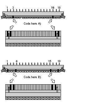
This section describes how to use terminal connector coding keys. It also provides an illustrated example of coded terminals.
Each I/O base has a series of slots into which you can insert one or more of the coding keys. Each terminal connector has a similar series of slots into which you can insert one or more of the coding tabs. When a key and a tab are inserted into slots that should mate, the I/O base and the connector cannot be physically connected.
NOTE: For maximum protection, key coding is required during installation.
An example of a key-coded screw-in terminals is shown in the figure below.
A)
Coding for Voltage Range I (≤ 42.4 VAC / ≤ 60 VDC) e.g. 24 VDC
B)
Coding for Voltage Range II (≥ 42.4 VAC / ≥ 60 VDC) e.g. 60 VDC 