|
Specifications
|
|
|
Original instructions
|
|
Module type
|
Power Supply
|
|
Nominal Input voltage
|
230 VAC or 120 VAC (jumper selectable)
|
|
Nominal Output voltage
|
24 VDC
|
|
Maximum Output Current (isolated)
|
0.7 A
|
|
Inputs
|
Self-restoring fuse
|
|
Outputs
|
Overvoltage protection: limited by a transzorb diode (type: SM6T30A)
|
|
Overload protection: by thermal current limiting (should the thermal current limiting respond, the input voltage must be switched -- off/on for reactivation).
|
|
Frequency
|
|
|
Input voltage
|
50/60 Hz + 5%
|
|
Internal chopper frequency
|
90 ... 110 kHz
|
|
Power
|
|
|
Efficiency
|
Typically 0.76 for IA = 0.7 A
|
|
Apparent power
|
Typically 32 VA for IA = 0.7 A
|
|
Effective power
|
Typically 21 W for IA = 0.7 A
|
|
Input/Output voltage
|
L, N, PE isolated from UB, M
|
|
Between base supply and ground
|
500 VDC, 1 min
|
|
Between input channels and ground
|
500 VDC, 1 min
|
|
Internal (not user-replaceable)
|
Internal self-restoring fuse
|
|
External
|
Min external F1: for 230 VAC, 0.315 A, slow-blow
Min external F1: for 120 VAC, 0.63 A, slow-blow
|
|
Inputs
|
None
|
|
Outputs
|
Green status LED for output voltage ok
|
|
Width
|
74.2 mm
|
|
Depth
|
40 mm
|
|
Length
|
141.5 mm
|
|
Regulations
|
VDE 0160, UL 508
|
|
Permissable operating and ambient temperatures
|
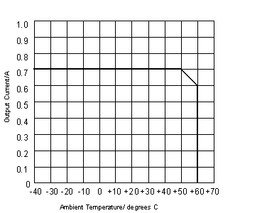
GUF (-40 ... +60 deg. C) adhering to DIN 40040, refer to the derating curve for uninhibited convection, operation orientation is vertical
|
|
Permissable storage temperature
|
-40 ... +85 deg. C
|
|
Internal power dissipation
|
Roughly 1.2 + 5 x IA (in W, IA in A)
|
|
Noise immunity
|
EN 50081-2
|
|
Safety classification
|
Class 1 (VDE 0160, IEC 1131-2)
|
|
Input Voltage
|
|
|
EX - EY not jumpered
|
L/N = 230 VAC
|
|
EX - EY jumpered
|
L/N = 120 VAC
|
|
Limiting Values
|
|
|
With jumper
|
100 Veff -15% to 120 Veff +10%
|
|
Without jumper
|
230 Veff -15% to 240 Veff +10%
|
|
Power Failure
|
|
|
Half wave loss at
|
100 Veff -15%
|
|
Min. of a half wave at
|
>= 100 Veff
|
|
Min. of a half wave at
|
230 Veff -15%
|
|
Input Current
|
|
|
For 85 Veff
|
Typically 0.366 Aeff, IA = 0.7 A
|
|
For 170 Veff
|
Typically 0.188 Aeff, IA = 0.7 A
|
|
For 230 Veff
|
Typically 0.188 Aeff, IA = 0.7 A
|
|
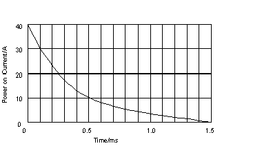
Power on Current
|
|
|
I2T
|
0.3 A2s
|
|
IT
|
0.02 As
|

|
Number
|
1 x UB = 24 VDC, max. 0.7 A, isolated
|
|
Limiting Values
|
|
|
UBmin
|
21 VDC
|
|
UBmax
|
30 VDC
|
|
Output Current
|
|
|
IA
|
0 ... 0.7 A
|
|
Output Ripple
|
|
|
Typical
|
150 mV/p-p (max. 20 MHz)
|
|
Max.
|
250 mV/p-p (max. 20 MHz) - measured with a 0.1 microF capacitor
|
|
Voltage Regulation
|
Typically +500 mV for 0.7A after 0.35 A
Typically -500 mV for 0.35A after 0.7 A
|
