Example for the PWM block
Original instructions
Overview
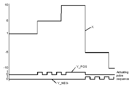
In the example, the signal sequences on the outputs Y_POS and Y_NEG are shown for various X input signal values. The examples differ with respect to their selected parameter assignments.
The following examples on the PMW function block are to be found in this section
Jump response 1
The following parameter specifications apply to the jump response 1 display:
Parameters
Specification
t_period
4 s
t_min
0.2 s
t_max
3.8 s
t_pause
0.1 s
t_brake
0.2 s
up_pos
10
up_neg
10
Jump response 1 timing diagram
X 
analog signal
It is easily seen that the time span in which output Y_POS carries "1" signal is directly proportional to input signal X. In addition, it can be seen that a short Y_NEG signal (output Y_NEG to 1-Signal) follows every Y_POS signal. This can be attributed to the non-"0" t_brake parameters. With negative X input signals, the signal duration for Y_NEG is proportional X. A short Y_POS pulse as brake pulse also follows the Y_NEG pulse here as well.
Jump response 2
The following parameter specifications apply to the jump response 2 display:
Parameters
Specification
t_period
4 s
t_min
0.5 s
t_max
4 s
t_pause
0 s
t_brake
0 s
up_pos
10
up_neg
10
Jump response 2 timing diagram
X 
analog signal
In contrast to the example "Jump response 1", here the pause and brake pulses are dropped, as the appropriate parameters were configured to "0". It is noticeable that pulses are no longer output for very small X input signals. This is directly attributable to the effect of time t_min. Moreover a continuous pulse is output for large X input signals (X = up_pos/up_neg). This is related to having selected t_max = t_period.