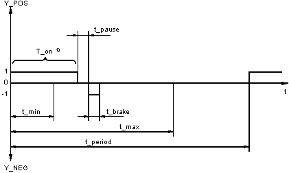
The period determines the time, in which the actuating pulses (1-signal on output Y_POS or Y_NEG) are regularly output, i.e. in a constant time-slot pattern.
The parameter
t_min specifies the minimum pulse length, i.e. the shortest time span for which the output
Y_POS or
Y_NEG should carry 1-signal. If the length of the pulse calculated according to the equation in the section
Pulse length formulas for Y_POS and Y_NEG is shorter than
t_min, then there will be no pulse throughout the whole period.
The parameter t_max specifies the maximum pulse length, i.e. the time span for which the output Y_POS or Y_NEG should carry 1-signal. If the value calculated for the pulse duration according to the above formula is greater than t_max, the pulse duration is limited to t_max. It is advisable to perform a freely definable pause time of t_pause = 10 or 20 ms between the actuating and brake pulses to protect the power electronics (hopefully preventing simultaneous firing of the anti-parallel connected converters).
Parameter t_pause specifies the time interval that should be waited after the "1" signal on output Y_POS (Y_NEG), before the opposite output Y_NEG (Y_POS) goes to "1" signal for time span t_brake. The action in question here is a brake pulse, which should take place after the pause time. A pause time of t_pause = 20 ms (t_pause =0.02) corresponds to an interruption of the firing angle control for two half waves.
That should guarantee a sufficiently large safety margin for the prevention of short-circuits resp. triggering of the suppressor circuitry as a consequence of anti-parallel thrystors firing.
An overview of the ratio between times is shown in the following diagram:
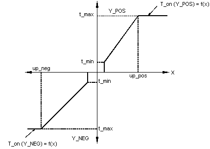
The parameters up_pos mark the point of input variable X, with which the output Y_POS would continuously carry a 1-signal, when the input variable X is positive.
t_pause = t_brake = 0
and
t_max = t_period.
The parameters up_neg mark the point of input variable X, with which the output Y_NEG continuously carries a 1-signal, when the input variable X is negative.
t_pause = t_brake = 0
and
t_max = t_period.
The dependency of the time duration in which the output Y_POS (Y_NEG) carries a 1-signal, on the input variable X is illustrated in the following diagram (again the figure has put t_pause = t_brake = 0).
In reset mode R = 1, outputs Y_POS and Y_NEG are set to "0" signal. The internal time meters are also standardized, so that the function block begins the transfer to R=0 with the output of a new 1 signal on the associated output.
If the PWM block is operated together with a PID controller, then the period t_period should be so selected, that it corresponds to the PID controllerís scan time. It is then guaranteed that every new actuating signal from the PID controller within the period time can be fully processed.
The PWM scan time should be in proportion with the period vs. pulse time. Though this the smallest possible actuating pulse will be specified.
The following ratio is recommended:


