Description
Original instructions
Using the block
Actuators are driven not only by analog quantities, but also by binary actuating signals. The conversion of analog values into binary output signals is achieved for example, through pulse width modulation (PWM) or pulse duration modulation (PDM).
The actuator adjusted average energy (actuator energy) should be in accord with the modulation block's analog input value (IN).
Function description
The PWM function block is used to convert analog values into digital output signals for Control Expert.
In the pulse width modulation (PWM1) a "1" signal of variable persistence proportional to the analog value X is output within a fixed cycle period. The adjusted average energy corresponds to the quotient of the switch on duration T_on and the cycle time t_period.
In order that the adjusted average energy also corresponds to the analog input variable IN, the following must apply:
NOTE: This function block performs an internal initialization in the first program cycle after a warm start or cold start (e.g. application download or power cycle) of the PLC program.
Due to this, you have to make sure that the function block is invoked in the first program cycle. In case of inkoving the function block in a later program cycle, the internal initialization will not be performed and the ouputs may deliver wrong values.
WARNING
UNEXPECTED OUTPUT BEHAVIOUR
Make sure that the function block is always invoked in the first program cycle.
Failure to follow these instructions can result in death, serious injury, or equipment damage.
EN and ENO can be configured as additional parameters.
General information about the actuator drive
In general, the binary actuator drive is performed by two binary signals Y_POS and Y_NEG.
On a motor the output Y_POS corresponds to the signal "clockwise rotation" and the output Y_NEG the signal "counter-clockwise rotation". For an oven the outputs Y_POS and Y_NEG could be interpreted as corresponding to "heating" and "cooling".
Should the actuating drive in question be a motor, it is possible that to avoid overtravel for non-self-locking gearboxes, a brake pulse must be output after the engage signal. In order to protect the power electronics, there must be a pause time after switching on T_on and before the brake pulse t_brake to avoid short circuits.
Pulse length formulas for Y_POS and Y_NEG
The pulse length T_on for outputs Y_POS and Y_NEG is determined by the following equations:
Output
Formula
Condition
Y_POS
Y_NEG
Parametering rules
For correct operation the following rules should be observed:
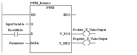
Representation in FBD
Representation:
Representation in LD
Representation:
Representation in IL
Representation:
CAL PWM_Instance (X:=InputVariable, R:=ResetMode, 
    PARA:=Parameters, Y_POS=>Positive_X_ValueOutput, 
    Y_NEG=>Negative_X_ValueOutput)
Representation in ST
Representation:
PWM_Instance (X:=InputVariable, R:=ResetMode, 
    PARA:=Parameters, Y_POS=>Positive_X_ValueOutput, 
    Y_NEG=>Negative_X_ValueOutput) ;
PWM parameter description
Description of input parameters:
Parameter
Data type
Description
X
Input variable
R
Reset mode ("1" = Reset)
PARA
Parameter
Description of output parameters:
Parameter
Data type
Description
Y_POS
BOOL
Output for positive X values
Y_NEG
BOOL
Negative X value output
Parameter description Para_PWM
Data structure description
Element
Data type
Description
t_period
Length of period
t_pause
TIME
Pause time
t_brake
TIME
Braking time
t_min
TIME
Minimum actuating pulse time (in sec)
t_max
TIME
Maximum actuating pulse time (in sec)
up_pos
Upper limit value for positive X values
up_neg
REAL
Upper limit value for negative X values
Runtime error
For a list of all block error codes and values, see CLC_PRO.