MFB Blocks and Basic Parameters
(Original Document)
Overview
Most blocks use the same input and output parameters, deemed basic.
The operating principle of the basic input and output parameters is explained below.
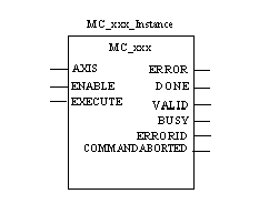
Representation in FBD
Representation:
Description of the Standard Input Parameters
The following table describes the input parameters:
Parameter
Type
Comment
AXIS
Axis_Ref type object, which defines the device
ENABLE
When ENABLE is TRUE, the parameters are taken into account and the function is executed.
As soon as ENABLE is FALSE, the output parameters, ERROR, DONE, and COMMANDABORTED, are immediately set to FALSE.
EXECUTE
On an EXECUTE rising edge, the parameters are taken into account and the function is executed.
When EXECUTE is TRUE, the output parameters, ERROR, DONE, COMMANDABORTED, and BUSY are controlled by the block.
When EXECUTE is FALSE, the BUSY output parameter is TRUE until the end of the block execution. As soon as one of the ERROR, DONE, or COMMANDABORTED output parameter changes to TRUE, they all become FALSE.
Description of the Standard Output Parameters
The following table describes the output parameters:
Parameter
Type
Comment
ERROR
ERROR is TRUE when an execution error is detected by the function block.
DONE
DONE is TRUE when the execution of the function is completed.
VALID
VALID is TRUE when the others are enabled.
BUSY
BUSY is TRUE to indicate that the execution of the function block is in progress.
BUSY is set to TRUE when EXECUTE switches to TRUE (on a rising edge), and is set to FALSE when one of the following status values, DONE, ERROR, or COMMANDABORTED switches to TRUE.
ERRORID
Error identifier.
COMMANDABORTED
COMMANDABORTED is TRUE when the execution of the block is cancelled. This cancellation is due to the execution of another command.
NOTE: The type of the output parameter ErrorId (Error Identifier) is UDINT for the blocks that use messaging (MC_READ..., MC_WRITEPARAMETER and CAN_HANDLER).
All blocks have the propriety of recording the last ERRID error in the Control_Expert DIAG BUFFER.
Block Operation with an Execute Input Parameter.
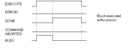
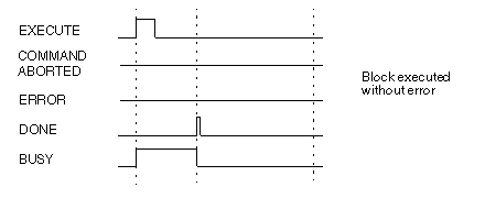
The figure below shows the time diagram of a block including an EXECUTE input parameter set to 1 until the block execution has completed (DONE=0 and BUSY=0), the block executes without any errors:
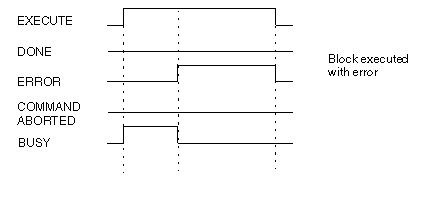
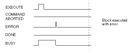
The figure below shows the time diagram of a block including an EXECUTE input parameter set to 1 until the block execution has completed (ERROR=0 and BUSY=0), the block executes with errors:
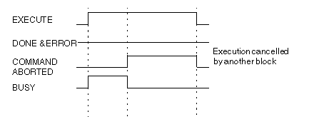
The figure below shows the time diagram of a block including an EXECUTE input parameter set to 1 until the block execution has completed (COMMANDABBORTED=0 and BUSY=0), the block execution was cancelled:
The figure below shows the time diagram of a block including an EXECUTE input parameter set to 1 on a PLC cycle, the block executes without any errors:
The figure below shows the time diagram of a block including an EXECUTE input parameter set to 1 on a PLC cycle, the block executes with any errors:
Block Operation with an Enable Input Parameter
The figure below shows the time diagram of a block including an ENABLE input parameter, execution is fast:
The figure below shows the time diagram of a block including an ENABLE input parameter, execution is normal (more than one PLC cycle):