The BMENOC0321 control network module is installed on a local Ethernet backplane in an M580 system. With the Ethernet backplane enabled, the BMENOC0321 provides access to the device network (through the external ports of the CPU).
Schneider Electric recommends the installation of a maximum of two BMENOC0321 modules in an M580 system to provide Ethernet transparency between a control network (for example, a SCADA system) and a device network. You can enable the
IP forwarding service on only one BMENOC0321 module per local rack.
In a Hot Standby system, the BMENOC0321 module uses the same IP+1 address as the BMENOC0301/11 module on the local rack. Confirm that you configure the IP address used in the BMENOC0301/11 module differently than the IP address of the BMENOC0321 module (for the control network and the fieldbus network when IP forwarding is enabled). Use an Ethernet manager tool to verify the system is working.
Device Network with DIO Ring and Control Network Architecture
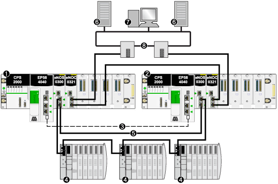
This Hot Standby system, which connects a single DIO ring (for example, SCADA) to your system, consists of the following:
-
two local Hot Standby racks, each containing a Hot Standby CPU with Ethernet I/O scanner service
-
BMENOS0300 module on the local rack connected to a DIO ring
-
BMENOC0321 control network module on the local rack providing transparency between the DIO ring and the control network
In this topology, no (e)X80 RIO drops are used. No sub-rings, and no are used.
The following example presents a Hot Standby system with a control network communicating with a DIO ring:
1
primary local rack with primary CPU
2
standby local rack with standby CPU
3
Hot Standby communication link
4
distributed equipment
5
DIO ring
6
SCADA server
7
engineering workstation
8
control room Ethernet network (with Gb RSTP ring)
NOTE: In this design:
-
Connect the two BMENOS0300 modules via a direct link.
-
If there is a break in the direct connection between the two BMENOS0300 modules, the Hot Standby system may report communication issues in case the Ethernet traffic is heavily loaded (bit HSBY_SUPPLEMENTARY_LINK_ERROR in ECPU_HSBY_STS). This information has no effect on system behavior and disappears as soon as the direct connection is restored. However, you need to repair the direct connection between the two BMENOS0300 modules so that the system can remain operational in case a second break occurs.
-
No link can be made connecting the dual Ethernet ports on the primary CPU to the dual Ethernet ports on the standby CPU.
-
Only one DIO ring is supported.
-
Set the rotary selectors on both of the BMENOS0300 modules to configure the top port as a service port, and the two lower ports as DIO ring ports.
Device Network with RIO Main Ring, DIO Sub-Ring, and Control Network Architecture
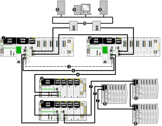
A Hot Standby system with an RIO main ring and a DIO sub-ring can be constructed using a BMENOS0300 module on an RIO drop on the main ring. In this design, the CPU scans the RIO drops and the distributed equipment.
Because the Ethernet backplane port of each BMENOS0300 module is enabled, connecting a dual Ethernet port on the primary CPU to a dual Ethernet port on the standby CPU in this case can cause the Hot Standby system to cease functioning.
The following example presents an RIO main ring, a DIO sub-ring (connected to the main ring via a BMENOS0300 module on an RIO drop), and a control network scanned by the CPU.
1
primary local rack with primary CPU
2
standby local rack with standby CPU
3
Hot Standby communication link
4
RIO main ring
5
(e)X80 RIO drop
6
distributed equipment
7
DIO sub-ring
8
SCADA server
9
engineering workstation
10
control room network (with Gb RSTP ring)
NOTE: In this design:
-
No link can be made connecting the dual Ethernet ports on the primary CPU to the dual Ethernet ports on the standby CPU.
-
Set the rotary selectors on the BMENOS0300 module to configure the top port as a service port, and the two lower ports as DIO sub-ring ports.
Device Network with RIO Main Ring, DIO Sub-Ring, DRSs, and Control Network Architecture
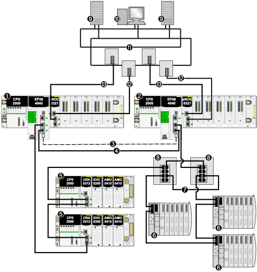
A Hot Standby system with an RIO main ring and a DIO sub-ring can be constructed using one or more dual-ring switches (DRSs) to connect the distributed equipment to the main ring. DRSs can also be used to connect the local rack to the control network.
Distributed equipment in a DIO sub-ring cannot be connected directly to the main ring. Only (e)X80 and Quantum RIO drops are allowed on the main ring.
The following example presents an RIO main ring, a DIO sub-ring (connected to the main ring via master/slave DRSs), and a control network scanned by the CPU:
1
primary local rack with primary CPU
2
standby local rack with standby CPU
3
Hot Standby communication link
4
RIO main ring
5
(e)X80 RIO drop
6
distributed equipment
7
DIO sub-ring
8
dual-ring switch (DRS) with C9/C10 downloaded pre-configuration file
9
SCADA server
10
engineering workstation
11
control room network (Gb RSTP ring)
No link can be made connecting the dual Ethernet ports on the primary CPU to the dual Ethernet ports on the standby CPU.
Device Network with RIO Main Ring, Isolated DIO Ring, and Control Network Architecture
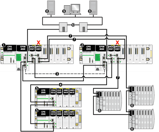
You can expand a simple RIO main ring by adding a DIO daisy chain (not a ring). The isolated distributed equipment in the DIO chain is scanned by a BMENOC0301.2 module (its Ethernet backplane connection disabled) on the local rack. A BMENOC0321 module is connected externally with an Ethernet cable to the BMENOC0301.2 module to provide transparency between the isolated DIO network and the control network.
The following example presents an RIO main ring, an isolated DIO ring (that communicates with the control network, not the device network), and a control network scanned by the CPU:
1
primary local rack with primary CPU
2
standby local rack with standby CPU
3
Hot Standby communication link
4
RIO main ring
5
(e)X80 RIO drop
6
distributed equipment
7
isolated DIO ring
8
SCADA server
9
engineering workstation
10
control room network (Gb RSTP ring)
X
Ethernet backplane connection disabled on the BMENOC0301 module to support the isolated DIO ring (7)
NOTE: Because the Ethernet backplane port of the BMENOC0301 module on the local rack is disabled, confirm that you connect externally the service ports of the BMENOC0301 module and the BMENOC0321 module.
Device Network with RIO Main Ring, DIO Sub-Ring, DRSs, and Dual Control Network Architecture
This topology is similar to the one previously discussed, except there is a dual connection in this architecture from the control network to the BMENOC0321 module on the local rack. Each physical connection from the control network to the BMENOC0321module belongs to a unique subnet.
Follow these steps to connect the BMENOC0321 modules on the local rack to the two different control room subnets:
|
Step
|
In the Primary Local Rack...
|
In the Standby Local Rack...
|
|
1
|
Connect the Ethernet control port of the BMENOC0321 module to subnet A from the control room.
|
Connect the Ethernet service port of the BMENOC0321 module to subnet A from the control room.
|
|
2
|
Connect the Ethernet service port of the BMENOC0321 module to subnet B from the control room.
|
Connect the Ethernet control port of the BMENOC0321 module to subnet B from the control room.
|
The following example presents an RIO main ring, a DIO sub-ring (connected to the main ring via master/slave DRSs), and a control network (with 2 subnets) scanned by the CPU
1
primary local rack with primary CPU
2
standby local rack with standby CPU
3
Hot Standby communication link
4
RIO main ring
5
(e)X80 RIO drop
6
distributed equipment
7
DIO sub-ring
8
dual-ring switch (DRS) with C9/C10 downloaded pre-configuration file
9
SCADA server
10
engineering workstation
11
control room network
12
subnet A from control room
13
subnet B from control room  CAUTION
  CAUTION
 CAUTION


