A simple M580 Hot Standby system includes, at minimum, two Hot Standby local racks, each containing a Hot Standby CPU with Ethernet I/O scanner service. The system also may include one or more of the following:
-
(e)X80 RIO drops, each containing a BM•CRA312•0 (e)X80 EIO adapter module, located on the main ring
-
Quantum RIO drops, each containing a Quantum adapter module, located on the main ring
-
distributed equipment, connected to the main ring via service ports of BM•CRA312•0 modules, but not residing directly on the ring
NOTE: Distributed equipment can be connected to the main ring by either:
These connections can be made, for example, via the service port of a ••• CRA 312 •• module, or through a BMENOS0300 network option switch module.
NOTE: Premium remote I/O drops are not supported in an M580 Hot Standby system.
This topic describes the following frequently used network topologies for Hot Standby systems:
-
a simple RIO main ring
-
a DIO ring connected to:
-
a BMENOS0300 module, in a design that supports up to 64 devices
-
a BMENOC0301/11 communication module, in a design that supports up to 128 devices
-
a DIO ring
-
an RIO main ring, with a DIO daisy chain
-
an RIO main ring, with a DIO ring
-
an RIO main ring, with a DIO sub-ring
-
an HMI connected to a Hot Standby topology
-
SCADA connected to a Hot Standby topology
NOTE: In a Hot Standby system, you can install only one main ring, which connects to the CPUs’ Ethernet backplanes. If your system contains an RIO main ring or a DIO ring that is connected to a non-isolated BMENOC0301/11 module on the local rack, verify that you isolate (disable the modules’ Ethernet backplane ports) other BMENOC0301/11 modules to which you connect a DIO ring.
You can have multiple BMENOC0301/11 modules in a local rack, each with its backplane port enabled, provided the Ethernet ports (the service port and the two network ports) are not used.
Simple RIO Main Ring Architecture
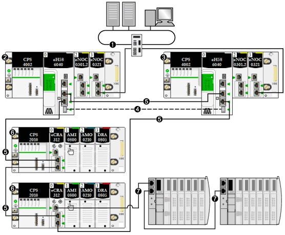
A Hot Standby system with an RIO main ring consists of the following:
-
two local Hot Standby racks, each containing a Hot Standby CPU with Ethernet I/O scanner service
-
one or more (e)X80 RIO drops or Quantum RIO drops, each containing an adapter module
In this topology, the (e)X80 RIO drops are connected directly to the main ring. No sub-rings, and no are used.
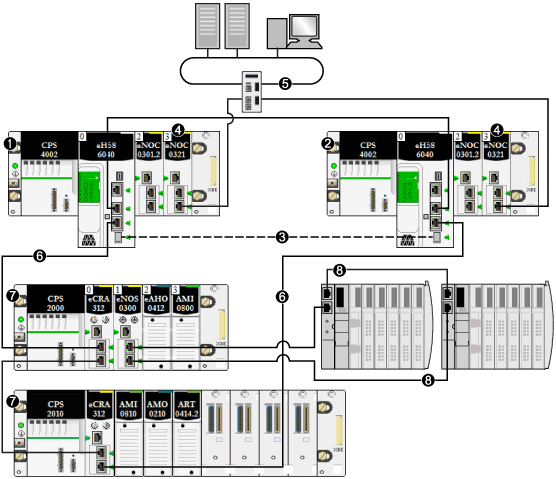
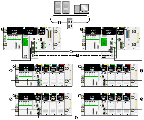
The following example presents a Hot Standby system with an M580 RIO main ring consisting of four (e)X80 RIO drops:
1
primary local rack with primary CPU
2
standby local rack with standby CPU
3
control network connected to a BMENOC0321 module on the local rack to provide transparency between the device network and the control network
4
Hot Standby communication link
5
RIO main ring
6
(e)X80 RIO drop
DIO Ring Architecture (up to 64 Devices)
A Hot Standby system with a DIO ring can be constructed using a BMENOS0300 module in place of a BMENOC0301/11 module. In this design, the CPU alone scans the distributed equipment.
NOTE: Use this design to scan up to 64 distributed equipment I/O points.
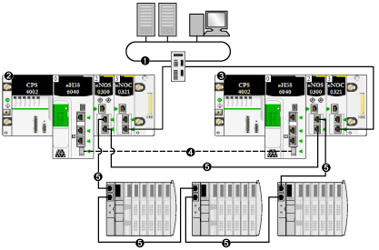
The following example presents a DIO ring scanned by the CPU via the BMENOS0300 modules.
Because the Ethernet backplane port of each BMENOS0300 module is enabled, connecting a dual Ethernet port on the primary CPU to a dual Ethernet port on the standby CPU in this case can cause the Hot Standby system to cease functioning:
1
control network connected to a BMENOC0321 module on the local rack to provide transparency between the device network and the control network
2
primary local rack with primary CPU
3
standby local rack with standby CPU
4
Hot Standby communication link
5
DIO ring
NOTE: In this design:
-
Up to 64 distributed devices can be included.
-
Connect the twoBMENOS0300 modules via a direct link.
-
If there is a break in the direct connection between the two BMENOS0300 modules, the Hot Standby system may report communication issues in case the Ethernet traffic is heavily loaded (bit HSBY_SUPPLEMENTARY_LINK_ERROR in ECPU_HSBY_STS). This information has no effect on system behavior and disappears as soon as the direct connection is restored. However, you need to repair the direct connection between the two BMENOS0300 modules so that the system can remain operational in case a second break occurs.
-
No link can be made connecting the dual Ethernet ports on the primary CPU to the dual Ethernet ports on the standby CPU.
-
Only one DIO ring is supported.
-
Set the rotary selectors on both of the BMENOS0300 modules to configure the top port as a service port, and the two lower ports as DIO ring ports.
DIO Ring Architecture (64 to 128 Devices)
A Hot Standby system with a DIO ring can be constructed using one or more BMENOC0301/11 modules to scan the distributed equipment.
Distributed equipment in a DIO ring cannot comprise the main ring. Only (e)X80 and Quantum RIO drops are allowed on the main ring.
NOTE: Use this design to scan 64 or more distributed equipment I/O points.
Distributed equipment in a DIO ring can be connected to the service port of a BMENOC0301/11 module. However, if the system also supports an RIO main ring, disable the backplane port of the BMENOC0301/11 module.
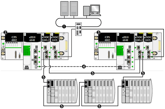
This example presents a DIO ring of distributed equipment scanned by BMENOC0301/11 modules:
1
control network connected to a BMENOC0321 module on the local rack to provide transparency between the device network and the control network
2
primary local rack with primary CPU
3
standby local rack with standby CPU
4
Hot Standby communication link
5
DIO ring
NOTE: In this design:
-
Up to 128 distributed devices can be included.
Of these 128 connections
-
Connect the two BMENOC0301/11 modules via a direct link.
-
In the
Services → RSTP page of the BMENOC0301/11 DTM in Control Expert, set the
Bridge Priority to
Root.
-
If there is a break in the direct connection between the two BMENOC0301/11 modules, the Hot Standby system may report communication issues in case the Ethernet traffic is heavily loaded (bit HSBY_SUPPLEMENTARY_LINK_ERROR in ECPU_HSBY_STS). This information has no effect on system behavior and disappears as soon as the direct connection is restored. However, you need to repair the direct connection between the two BMENOC0301/11 modules so that the system can remain operational in case a second break occurs.
-
Because this design employs a non-isolated BMENOC0301/11 module with its Ethernet backplane port enabled no link can be made connecting the dual Ethernet ports on the primary CPU to the dual Ethernet ports on the standby CPU.
-
Up to five additional BMENOC0301/11 modules can be added to both the primary and standby local racks, as part of the single DIO ring supported in this design.
-
Only one DIO ring is supported.
Simple RIO Main Ring with DIO Daisy Chain Architecture
You can expand a simple RIO main ring by adding a DIO daisy chain (not a ring). The distributed equipment can be part of either an (e)X80 or Quantum RIO drop. In this example, an (e)X80 RIO drop is used.
In this example, the distributed equipment is connected to the service port of an BMECRA31210 eX80 performance EIO adapter module:
1
control network connected to a BMENOC0321 module on the local rack to provide transparency between the device network and the control network
2
primary local rack with primary CPU
3
standby local rack with standby CPU
4
Hot Standby communication link
5
RIO main ring
6
(e)X80 RIO drop
7
DIO daisy chain (non-ring)
NOTE: In this design:
-
Each BMENOC0301/11 module on the local rack is connected to the Ethernet backplane, by enabling its Ethernet backplane port.
-
Up to 31 RIO drops can be included.
-
Up to 64 distributed devices can be scanned by the Hot Standby CPUs.
-
Up to 128 distributed devices can be scanned by non-isolated BMENOC0301/11 modules.
Of these 128 connections:
Simple RIO Main Ring with DIO Ring
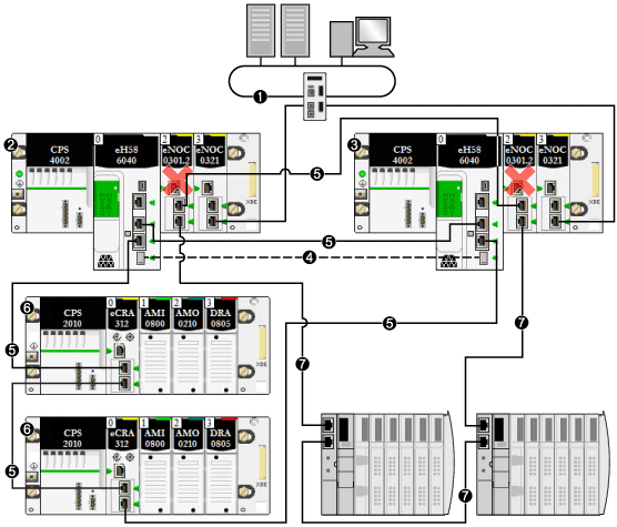
You can design a Hot Standby system to include dual rings: an RIO main ring and a DIO ring. In this design, the CPU scans the RIO main ring and a BMENOC0301/11 module scans the distributed equipment.
In the following example, the BMENOC0301 module scanning the distributed equipment is isolated. To isolate the communication module, disable its Ethernet backplane port. In this design, X Bus backplane communication remains enabled for the communication module.
The (red) X indicates that the BMENOC0301 module is isolated from the Ethernet backplane:
1
control network connected to the BMENOC0321 module on the local rack providing transparency between the device network and the control network
2
primary local rack with primary CPU
3
standby local rack with standby CPU
4
Hot Standby communication link
5
RIO main ring
6
(e)X80 RIO drop
7
DIO ring
Simple RIO Main Ring with DIO Sub-Ring
You can design a Hot Standby system to include both an RIO main ring and a DIO sub-ring. In this design, the CPU scans the RIO main ring, and the BMENOC0301 module scans the distributed equipment. The DIO sub-ring is connected to the RIO main ring via a BMENOS0300 module in an (e)X80 RIO drop.
NOTE: In this design, the rotary selectors on the BMENOS0300 module (that is connected to the DIO sub-ring (7)) are set to configure the top port as a service port and the two lower ports as DIO sub-ring ports.
Unlike the prior example, the BMENOC0301 module scanning the distributed equipment is not isolated. Confirm that its Ethernet backplane port is enabled:
1
primary local rack with primary CPU
2
standby local rack with standby CPU
3
Hot Standby communication link
4
BMENOC0321 module on the local rack, providing transparency between the device network and the control network
5
control network
6
RIO main ring
7
(e)X80 RIO drop
8
DIO sub-ring
Connecting an HMI to a Hot Standby Topology
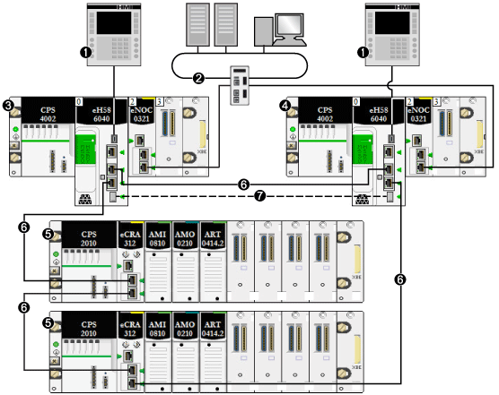
You can connect an HMI directly to a Hot Standby CPU. To access the local PACs (for diagnostics and control), connect an HMI to both the primary and standby CPUs. In the following example, the connection is made via the USB port of each CPU. This design allows access for diagnostics and control to the service port of either or both CPU:
1
HMI
2
control network connected to the BMENOC0321 module on the local rack providing transparency between the device network and the control network
3
primary local rack with primary CPU
4
standby local rack with standby CPU
5
(e)X80 RIO drop
6
RIO main ring
7
Hot Standby communication link
You can connect an HMI to a Hot Standby system in several ways. Two examples are presented below:
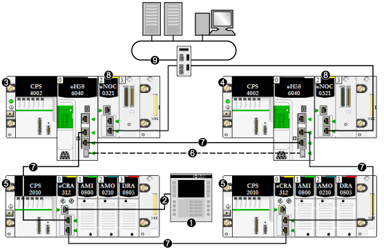
Alternatively, you can indirectly connect an HMI to a Hot Standby CPU. In the following example, the connection is made via the service port of a BMECRA312•0 module on the RIO main ring. In this design, only one HMI is required. The service port and USB port on both CPUs can be accessed for diagnostics and control:
1
HMI
2
Ethernet connection to the service port of the BMECRA312•0 module
3
primary local rack with primary CPU
4
standby local rack with standby CPU
5
(e)X80 RIO drop
6
Hot Standby communication link
7
RIO main ring
8
BMENOC0321 module on the local rack providing transparency between the device network and the control network
9
control network
Simple Solution for Connecting an Engineering Tool to a Hot Standby Topology
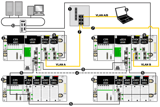
The following topology presents a simple example of how to connect a PC running an engineering tool (for example, Control Expert) to the Hot Standby system. In this example:
-
The PC is equipped with a network interface card (NIC) that supports communication on multiple VLANs, in this case VLAN A and VLAN B.
-
The BMENOC0301/11 module in the primary PAC belongs to VLAN A.
-
The BMENOC0301/11 module in the standby PAC belongs to VLAN B.
1
layer 2 switch linking control network to the RIO main ring
2
primary local rack with primary CPU
3
standby local rack with standby CPU
4
Hot Standby communication link
5
RIO main ring
6
(e)X80 RIO drop
7
redundant link to the Hot Standby system
8
engineering tool resident on a PC
9
BMENOC0321 module on the local rack providing transparency between the device network and the control network
10
control network
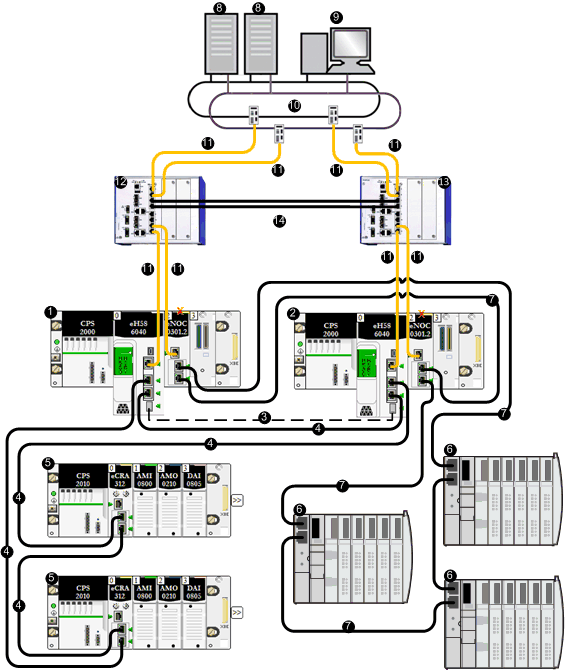
Connecting SCADA to a Hot Standby Topology
The following network topology shows you how to connect a SCADA server located on a redundant control network to the Hot Standby process control system:
1
local rack with CPU A
2
local rack with CPU B
3
Hot Standby communication link
4
RIO main ring
5
(e)X80 RIO drop
6
distributed equipment
7
DIO ring
8
SCADA server
9
engineering workstations
10
control network
11
layer 3 redundant link
12
layer 3 switch configured with virtual router redundancy protocol (VRRP), configured as master
13
layer 3 switch configured with VRRP, configured as slave
14
layer 2 ring between L3 switches
X
Indicates the BMENOC0301 module is isolated from the Ethernet backpl.ane
NOTE: In the preceding example, the L3 switches are Hirschmann dual-ring switches (DRSs), part number: RSPE30-24044 O7T99-SCCZ999HHSE3S04.0.
 CAUTION
  CAUTION
 CAUTION
 CAUTION
 CAUTION
 CAUTION
 CAUTION