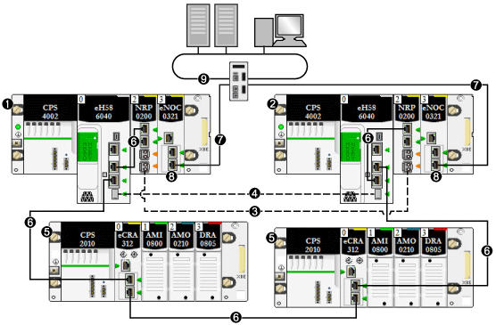
Linking Primary and Standby PACs
The BMEH58•040 and BMEH58•040S primary and standby PACs are connected by a Hot Standby link, and may also be connected by an Ethernet link.
NOTE:
-
Every M580 Hot Standby system design includes a Hot Standby link.
-
The Ethernet link provides a redundant path on the main ring. Its presence helps prevent the occurrence of two primary PACs. Although the system can function without an Ethernet link connecting the primary and standby PACs, such a system is not optimal.
NOTE: For a description of maximum lengths between (e)X80 RIO drops, refer to the topic Planning the Appropriate Network Topology in the Modicon M580 System Planning Guide for Frequently Used Architectures.
Hot Standby Link Between Primary and Standby PACs
Each BMEH58•040 and BMEH58•040S CPU is fitted with an
SFP socket for an SFP transceiver, which can be either:
Your choice of connector determines the maximum distance of the Hot Standby physical link.
|
SFP transceiver name
|
Media
|
Maximum Hot Standby Link Length
|
|
490 NAC 01 00
|
CAT 5e copper wire1
|
100 m (328 ft)
|
|
490 NAC 02 01
|
Single mode fiber optic cable
|
up to 15 km (9.3 mi)
|
|
1. Compatible with Gigabit data transfer rate.
|
NOTE: BMXNRP020• fiber converter modules cannot be used on the Hot Standby link.
Ethernet Link Between Primary and Standby PACs
The primary and standby BMEH58•040 or BMEH58•040S PACs can also be connected to each other by an Ethernet link. This link is typically part of an Ethernet RIO main ring, to which each Hot Standby CPU is connected.
Each BMEH58•040 and BMEH58•040S CPU includes two RJ45 connectors dedicated for use as a dual port to the main ring.
To create the Ethernet link between the primary and standby PACs, connect one of the dual Ethernet ports on the primary CPU to a dual Ethernet port on the standby CPU. You can do this in one of the following ways:
-
Directly connect the primary and standby CPUs using CAT-5e copper wire.
-
-
Connect each CPU to a BMXNRP0201 fiber converter module, then connect the two BMXNRP0201 modules with single-mode fiber optic cable, as described below:
1
primary local rack with primary CPU
2
standby local rack with standby CPU
3
Ethernet RIO fiber optic link between primary and standby CPUs (part of Ethernet RIO main ring)
4
Hot Standby fiber optic communication link
5
(e)X80 EIO drop
6
Ethernet RIO main ring
7
BMENOC0321 control network module redundant link
8
BMENOC0321 control network module providing transparency between the device network and the control network
9
control network
Like the Hot Standby link, your choice of connector and wiring determines the maximum distance of the Ethernet physical link:
