|
Modicon M580 Typical System Introduction
|
|
|
Original instructions
|

 WARNING WARNING |
|
UNEXPECTED EQUIPMENT BEHAVIOR
Failure to follow these instructions can result in death, serious injury, or equipment damage.
|
|
Phase
|
Feature
|
Description
|
|---|---|---|
|
design phase
|
standard
|
reduce the learning and engineering time (use standard Ethernet technology, Modicon X80 common modules,and Control Expert software for device configuration
|
|
open
|
collaborate with third-party solutions
|
|
|
flexible
|
adapt the control architecture to the plant topology
|
|
|
efficient
|
design the solution without constraints
|
|
|
operation phase
|
transparent
|
provide access to I/O modules and devices from the control network
|
|
accessible
|
change configuration without stopping the process, get diagnostic information from any location in the network, no switch required to create a complete M580 system
|
|
|
renew phase
|
sustainable
|
preserve long-term investment, allow smooth migration
|

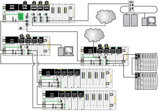
1An M580 CPU with Ethernet I/O scanner service on the local rack is connected to the RIO main ring. (For the Ethernet I/O scanner service, select a CPU with a commercial reference that ends in 40.)
2A BMENOS0300 network option switch module on the local rack connects a DIO cloud to the RIO main ring.
3A BMENOC0301/BMENOC0311 Ethernet communication module, connected to the CPU through the Ethernet backplane, manages distributed equipment on the device network.
4A BMENOC0321 control network module on the local rack creates transparency between the device network and the control network.
5A PC for port mirroring is connected to the service port of a BMECRA312•0 (e)X80 EIO adapter module.
6A BMENOS0300 network option switch module on an RIO drop manages an RIO sub-ring.
7A DIO cloud is connected to the service port of a BMECRA31210 eX80 performance EIO adapter module.
8A BMENOS0300 network option switch module on an RIO drop connects a DIO sub-ring to the RIO main ring.