Predefined Configuration File Name
C7_Master_RIOMainRing_RIOSubRing_DIOCloudsVx.xx.cfg, where
Vx.xx references the version number of the file.
Use of this Predefined Configuration
One of the many advantages of using the M580 architecture is to put some or all of your RIO drops on sub-rings. The RIO drops on the sub-rings are controlled by the PLC on the main ring the same way as RIO drops connected directly to the main ring. The sub-ring architecture lets you extend the distance between consecutive RIO drops and isolate the devices and cables on a sub-ring from those on the main ring and on other sub-rings.
With this predefined configuration, use 2 — one installed with this
master predefined configuration and the other installed with the corresponding
slave predefined configuration (
C8) — to provide a redundant connection between the main ring and the sub-ring. The
master DRS passes data between the main ring and the RIO sub-ring. If the
master DRS becomes inoperable, the
slave DRS takes control and passes data between the main ring and the RIO sub-ring.
NOTE: When a master slave becomes inoperable, a slave DRS assumes the primary role in less than 50 ms. Refer to the Comparison of Master/Slave Configuration and Auto Configuration topic to determine what roles the master and slave DRSs resume if the master DRS becomes operational again.
NOTE:
DRS inner ports are the 2 ports on the switch that are connected to the main ring. When using two DRSs, connect the designated master inner ports to the designated slave inner ports.
-
For copper port master and slave DRS redundant configurations, the inner ports (port 2) connect to each other for the main ring, and port 6 on both DRSs connect to each other for a sub-ring.
-
For copper/fiber port master and slave DRS redundant configurations, the inner ports (port 3) connect to each other for the main ring, and port 6 on both DRSs connect to each other for a sub-ring.
If you are using a single DRS but plan to convert to redundant configurations in the future, record these port configurations to reduce the number of any schematic changes required because of the conversion.
Devices Supported and Restricted in this Predefined Configuration
The predefined configuration described here is for a TCSESM083F23F1 ConneXium extended managed switch, which has 8 copper connection ports and no fiber port connections.
An RIO sub-ring can contain only approved Schneider Electric RIO modules.
Distributed equipment, such as TeSys T motor drives and islands of STB devices, can be connected to switch ports that are not reserved for main ring and RIO sub-ring connections. Each cloud uses only one DRS port connection. You cannot use this predefined configuration to connect distributed equipment directly on the sub-ring.
You cannot use a redundant pair of DRSs to connect a sub-ring to another sub-ring.
Do not connect any devices between the master DRSs and the slave DRS on the main ring or the sub-ring. Install the DRSs next to each other — within 100 m.
Predefined Port Connections
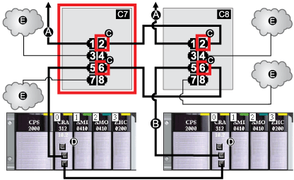
Use the 2 top ports (shown as 1 and 2 in the following graphic) for main ring (A) redundant connections. Use ports 5 and 6 for the RIO sub-ring (B) redundant connections.
Ports 3, 4, and 7 are configured for connecting DIO clouds to the network. Port 8 is reserved for
port mirroring (to monitor the status of the ports you previously selected in the switch’s port mirror web page).
NOTE: The default configuration of port 8 has port mirroring disabled.
C7
This master DRS uses a C7 predefined configuration file to act as the primary redundant connection between the main ring and the RIO sub-ring.
C8
This slave DRS uses a C8 predefined configuration file to act as the standby redundant connection between the main ring and the RIO sub-ring.
A
DRS connection to the main ring
B
DRS connection to the RIO sub-ring
C
DRS inner ports (The master and slave DRSs are linked together through ports 2 and 6. Ports 1 are linked to the main ring, and ports 5 are linked to the sub-rinig.)
D
These RIO drops have BM•CRA312•0 X80 EIO adapter modules.
E
DIO clouds
This table describes the functionality of the ports in the above illustration:
|
Port
|
Type
|
Description
|
|
1
|
100Base-TX
|
copper main ring redundant connection
|
|
2
|
100Base-TX
|
copper main ring redundant connection
|
|
3
|
100Base-TX
|
DIO cloud connection
|
|
4
|
100Base-TX
|
DIO cloud connection
|
|
5
|
100Base-TX
|
copper RIO sub-ring redundant connection
|
|
6
|
100Base-TX
|
copper RIO sub-ring redundant connection
|
|
7
|
100Base-TX
|
DIO cloud connection
|
|
8
|
100Base-TX
|
port mirroring connection
|
Except when enabling or disabling ports that are not connected to either a main ring or a sub-ring, do not adjust the configuration parameters or alter the port usage in the predefined configuration file. Changing the configuration parameters or the port assignments can compromise the effectiveness and accuracy of the switch, as well as the performance of the RIO network.
Port mirroring is disabled by default. If you enable port mirroring, you can select the ports on which you want to analyze traffic as the source ports. Ports 1-7 can be selected as source ports. Port 8 is the destination port, and it cannot be changed.


 WARNING