Configuration switch pack
The B875111 can be configured to accept 8 differential or 16 single ended inputs. When selected for 8 differential inputs, the card is called a B875111. When selected for 16 single ended inputs, the card is called a B877111.
This selection is made by switch 7 on the configuration switch pack found at the rear of the module. SW7 in the left position is equal to 16 inputs, in the right position it is equal to 8 inputs.
In addition to selecting the number of inputs, you also select voltage range, output format, polarity, offset and number of samples. Refer to the installation instructions and the DIP-switch chart on the left side of the module for details.
For a quick start setup, use the following settings to interface a 0 to +10 V input signal. For the following input parameters:
Set the switch settings as follows:
Input type selection (voltage or current)
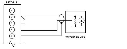
If configured as a B875 (8 differential inputs), current inputs (420 mA) are selected by placing a jumper at the field connector between the positive voltage input and the current input terminal for the appropriate channel. Refer to the following illustration.
Field connector jumper diagram
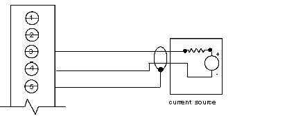
If configured as a B877 (16 single ended current inputs), input type is selected by the switches on the left side of the module. There is one switch for each of the 16 inputs. This switch places a 250 Ω precision resistor between the plus input and analog return. External jumpers are not used and must be removed. The left position is equal to voltage input, and the right position is equal to current input.
The fifth switch on switch bank 4 (left side) selects the voltage range for both B875 and B877 operations. This switch must correspond to switch 8 of the configuration switch bank (at rear of module). The left position of SW5 is equal to 10 volts, and the right position is equal to 5 volts. SW8 must be in the same position as SW5.
For the 010 V input signal example, set all the input switches to the left (down or towards the numbers).
If setup for 8 differential inputs, the module type will be a B875 and requires 8 consecutive 3xxxx binary registers. If setup for 16 single ended inputs, the module type will be a B877 and require 16 consecutive 3xxxx binary registers.
NOTE: Upon power-up the module s active indicator flashes rapidly showing that communication with the programmable controller has been established but, that the input data being returned is not valid. (4000 Hexadecimal is sent to the controller during the initialization time). When module initialization is complete, and valid input data is being transferred, the indicator is either steady on, or flashing slowly when any input is out-of-range.
The B875111 and B877111 require a high-density connector, part number AS8535000. Refer to the left side of the module for pinouts. Refer to the following illustration.
010 V input example.
The B875111 and B877111 will perform an analog to digital conversion on the inputs. The resolution of the analog to digital conversion is dependent upon the input range and output format selected with the configuration switch bank.
Using a programmer, call up the appropriate registers assigned in the I/O Map. Vary the input signal and check that the register content varies correctly.
Refer to the following table for the quick-start example.
|
Voltage
|
Value
|
|
@ 0 V
|
3xxxx=001 (decimal)
|
|
@ 5 V
|
3xxxx=3750
|
|
@ 10 V
|
3xxxx=7500
|
|
@ 11 V
|
3xxxx > 9999 (decimal)*
*The active light indicator should be flashing, indicating the input is out of range.
|
Sample Averaging Input Data
The output data can be processed by a low-pass digital filter in the module to average out and remove any low-frequency noise in the converted input analog data. The digital filter algorithm is:
where
Xn = Current input data sample
Yn = New output filter data value
Yn-1 = Previous output filter data value.
The digital filter algorithm approximates a classical exponential response characteristic with both the cut-off frequency, Fc, and the time constant, Tc, related to the number of samples to be averaged, N, and the throughput time, T. The "N" is user selected (8,16,32) with DIP-switches. Throughput time,"T", equals 10 ms for the B875111, and 20ms, for the B877111.)
where Pi = 3.141
As with any filter, the user must establish what time constant and cut-off frequency is suitable for the specific application. Below is a reference table that approximates the digital filter characteristics for various user settings.
Digital filter approximates (B875-111)
|
Throughput Time (T)
|
Number of Samples (N)
|
Cut-off Frequency (Fc )
|
Time Constant (Tc )
|
|
10 ms
|
8
|
1 Hz
|
160 ms
|
|
10 ms
|
16
|
0.5 Hz
|
320 ms
|
|
10 ms
|
32
|
0.25 Hz
|
1640 ms
|
Digital Filter Approximates (B877-111)
|
Throughput Time (T)
|
Number of Samples (N)
|
Cut-off Frequency (Fc )
|
Time Constant (Tc )
|
|
20 ms
|
8
|
0.5 Hz
|
320 ms
|
|
20 ms
|
16
|
0.25 Hz
|
640 ms
|
|
20 ms
|
32
|
0.125 Hz
|
1280 ms
|
Approx. step settling-time to 63% of final value = 1 x Tc
Approx. step settling-time to 99% of final value = 4.5 x Tc
Approx. step settling-time to 99.9% of final value = 6.8 x Tc
NOTE: As the scan time increases, the average response time may decrease as viewed in ladder logic.
In many applications, analog signals are provided to operators in units (points, gallons per second, degrees C, feet per minute, etc.) via LED displays, CRT monitors or report printouts. An analog input can be scaled to engineering units.
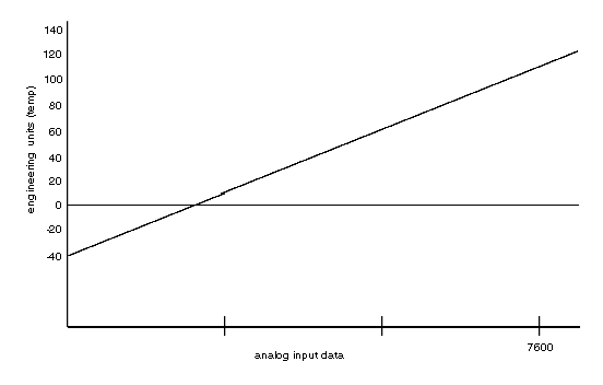
To illustrate the technique, assume that the010 V signal in the quick-start example represents a temperature from -40+140°F. Refer to the following illustration showing the signal to temperature relationship.
Signal to temperature relationship diagram
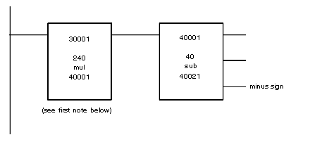
Scaled value from analog signal, diagram
NOTE: The logic shown is used to generate the scaled value in register 40020 from the analog signal in 3001. For example: 30001 = 3800; 40020 = 0051°F
NOTE: Only the high-order result of the multiplication is used, and no compensation for round-off is used in this example.


