|
B875–200 Configurable A/D Input, Calibration
|
|
|
(Original Document)
|

|
Step
|
Action
|
|---|---|
|
1
|
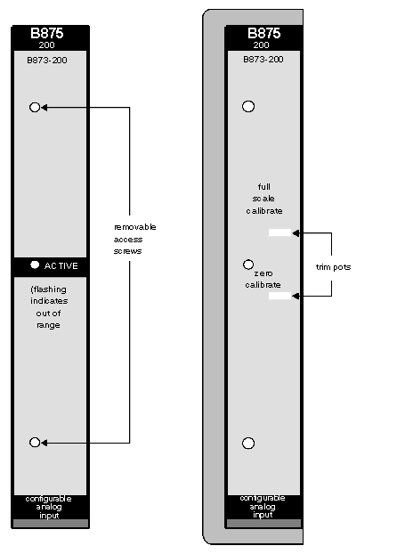
To access both trim pots, remove two screws and label located on front panel of module, as shown on location of trim-pot diagram, above.
Note: The top trim-pot adjusts the total magnitude of the range (full scale). The bottom trim-pot adjusts the zero offset scale.
|
|
2
|
Open module handle to expose connectors and terminals.
|
|
3
|
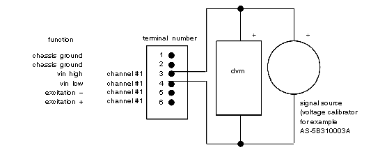
Install an input pack in any channel, and connect an appropriate signal source to that channel. Refer to voltmeter connections diagram, below.
|
|
4
|
Apply input signal to selected channel which represents zero signal (zero volts when using analog, V input pack, low bandwidth, 0 to +10 V (AS--5B31003A). On programming panel observe input from B875 for selected channel. Adjust zero cal control (R29) as required to read 0000.
|
|
5
|
Apply input signal that results in output between 80 to 90% of full scale. Use 9.375 V if calibrating with an analog, V input pack, low bandwidth, 0 to +10 V (AS--5B31003A). Resultant reading should be set for 0F00 Hex, or 3840 decimal with full scale calibration control (R57).
|
|
6
|
Repeat previous two steps until readings are correct at both zero and near-full-scale points.
|
|
7
|
After calibration is complete, disconnect voltmeter, return connections to their original state, close module handle, and replace front label that covers trim-pot.
|
