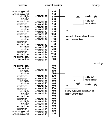
The module may be wired to accept the following types of packs: current input type; voltage input type; RTD input type; linear thermocouple input type; strain gauge/load cell input type. These input types and their connections are discussed below. Refer to the diagram showing the typical field circuit connections for current inputs, below.
Typical field circuit connections for current inputs, diagram
NOTE: A precision 20 Ω fusible resistor must be installed in each current input channel. The fusible resistor is supplied with each 4 - 20 mA or 0 - 20 mA input pack. The B875-200 may be installed in either the sinking or sourcing configuration.
Each channel is floating. Should you need a ground, you may tie one side of field wiring to chassis ground or use shield wiring with shield tied to chassis ground. Refer to note
Low Bandwidth Current Inputs (AS-5B32)
Select the channels to be used for current input packs. Current inputs are selected by inserting the input pack, together with a fusible resistor beside the pack, for the appropriate channel. Refer to the typical field circuit connections for current inputs diagram, above, while connecting the field-side wiring to the proper pins on the field connector.
NOTE: All input packs provide 1500 Vac/2500 Vdc isolation from bus to field wiring. Since any floating inputs may be exposed to static charges as high as 15 kV, connect one of the signal input leads to chassis ground either directly or through a resistor in the range of 1kW—10MW. Use the chassis ground at terminals 1, 2, 39 or 40. If the signal source used with an input has a dc signal path to chassis ground, no additional path is required at the B875 end of the field wiring.
NOTE: Channels are set independently. Any of the pack types identified above can be intermixed.
Low and Wide Bandwidths (AS–5B30/31 and AS–5B40/41) Voltage Inputs
Note the channels to receive the voltage inputs. Voltage inputs are selected by inserting the input pack for the appropriate channel. Refer to the following drawing, and connect field-side wiring to the proper pins on the field connector.
Typical field circuit connections for voltage inputs, diagram
NOTE: Voltage wide bandwidth input packs are significantly more sensitive to noise on input lines. Low bandwidth packs are recommended for general purpose input voltage usage.
NOTE: The shield-type shown is recommended. One side of the signal source may be connected to chassis ground when using twisted pair wiring.
NOTE: Channels are set independently. Any mixture of current, voltage, RTD, linear thermocouple, or strain gauge/load cell may be used as inputs.
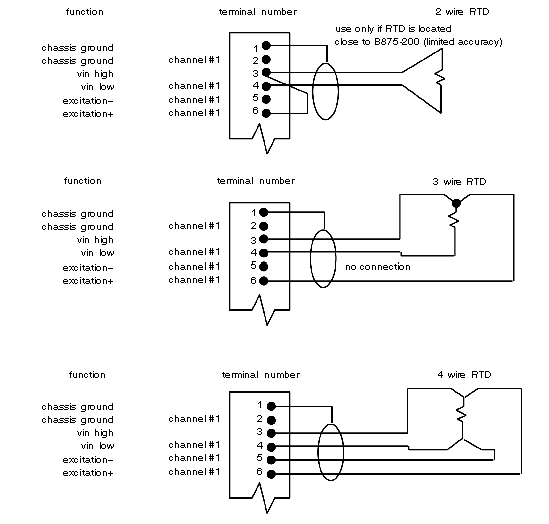
Note the channels designated to receive RTD inputs. RTD inputs are selected by inserting the input pack for the appropriate channel. Refer to the diagram below and connect the field-side wiring to the proper pins on the field connector.
Typical field circuit connections for RTD inputs, diagram
NOTE: The shield-type shown is recommended. One side of the signal source may be connected to chassis ground when using twisted pair wiring.
NOTE: Channels are set independently. Any mixture of current, voltage, RTD, linear thermocouple, or strain gauge/load cell may be used as inputs.
Linear Thermocouple (AS-5B47)
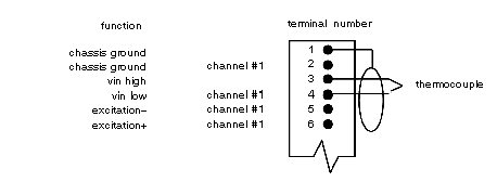
Note the channels designated to receive linear thermocouple inputs. Linear thermocouple inputs are selected by inserting the input pack for the appropriate channel. Refer to the diagram below and connect the field-side wiring to the proper pins on the field connector.
Typical field circuit connections for linear thermocouple inputs, diagram
NOTE: Thermocouple must be of the type designated by the dash number of the AS-5B47 input pack in use. Cold junction compensation is done by a temperature sensor located immediately behind the connector block.
NOTE: The shield-type shown is recommended. One side of the signal source may be connected to chassis ground when using twisted pair wiring.
NOTE: Channels are set independently. Any mixture of current, voltage, RTD, linear thermocouple, or strain gauge/load cell may be used as inputs.
Strain Gauge/Load Cell, 0—+5 V Output (AS–5B38)
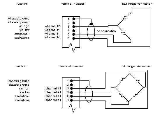
Note the channels designated to receive strain gauge/load cell inputs. Strain gauge/load cell inputs are selected by inserting the input pack for the appropriate channel. Refer to the diagram below and connect the field-side wiring to the proper pins on the field connector.
Typical field circuit connections for strain gauge/load cell inputs
NOTE: Connection must be such that strain in normal direction of application reuslts in a positive output voltage applied to vin high. Wiring to pins 5 and 6 may be reserved if output negative.
NOTE: The shield-type shown is recommended. One side of the signal source may be connected to chassis ground when using twisted pair wiring.
NOTE: Channels are set independently. Any mixture of current, voltage, RTD, linear thermocouple, or strain gauge/load cell may be used as inputs.
Use the following procedure to secure the module.
|
Step
|
Action
|
|
1
|
Reinstall any module temporarily removed
|
|
2
|
When using key pins (provided with housing shipment), install them above and below housing slot selected.
|
|
3
|
Carefully insert module into housing firmly, seating edge connector in backplane.
|
|
4
|
Secure module to housing using captive slotted mounting screws at top and bottom of module’s front panel.
|
|
5
|
Locate write-on label plate (Part No. AS-157A-000). Write input pack catalog numbers and input register numbers for each installed input pack.
|
|
6
|
Insert write-on label plate on right side of installed module. Using two standard screws supplied, tighten them into upper and lower portions of housing slot as shown in following diagram.
|
Write-on label plate placement, diagram
NOTE: Ensure that all input packs are removed prior to returning module for repair.


