|
B875–200 Configurable A/D Input, Module Configuration
|
|
|
(Original Document)
|
|
Step
|
Action
|
|---|---|
|
1
|
Locate eight-position DIP switch on rear of module.
Note: These DIP switches are used to select the desired number of channels, from 1—8.
|
|
2
|
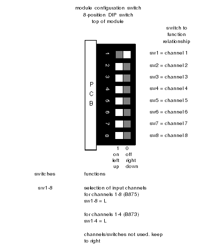
Set DIP switches based upon intended application prior to installation. Refer to module configuration DIP switch settings diagram, below, and to label located on left side of analog input module.
Note: The analog input module is shipped with channel 1 ON, B873), DIP switch (SW1) set to ON. The module is I/O mapped as a B873 when only channels 1—4 are in use. The module is I/O mapped as a B875 when more than 4 channels are in use.
|
|
3
|
Ensure all unused DIP switches are kept to the right.
|

|
Step
|
Action
|
|---|---|
|
1
|
Locate access hole on left side of module.
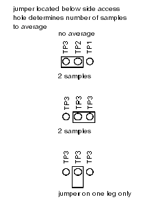
Note: This hole allows access to three leads and a two-position jumper, that selects the number of samples to be averaged per input channel: 0, 2, 4 samples to be averaged.
|
|
2
|
Select either 0, 2 or 4 samples to be averaged.
|
|
3
|
Set desired averaging prior to installation. Refer to jumper settings diagram, below, and label located on left side of module.
Note: The module is shipped with the jumper set for four samples.
Module configuration DIP switch settings, diagram
 Note: Sample averaging helps reduce the impact of serious noise on the input.
|