B873-002 and B875-002 Installation
(Original Document)
Installing the Module
Remove the module from the box and check for damage. If damage is found, contact your salesman or distributor for correct return procedure.
Set switch three to the module run position, and switch four to the data range selected for input - either standard or eevated - before inserting the module into the housing. (Refer to Switch Settings).
Module Characteristics
The following figure shows the 873 / 875 module, at pre-installation.
Included with the module is an analog connector set (Part# AS-8533-001 for B873-002 and Part# AS-8533-002 for B875-002).
The connector set consists of two mounting screws, a wire duct, and either one (B873-002) or two (B875-002) field wiring connectors. Each connector has eighteen recessed slotted screw terminals and can accept various wire gauges, but 16 to 20 gauge is recommended for the field side wiring.
NOTE: The wiring connections can only be made with an 1/8 inch blade screwdriver.
The connector plugs into the module with the field wiring to the left. The removable connector permits module removal and replacement without disturbing the wiring. Refer to the diagram for the terminal numbering for the terminal functions.
The wire duct protects the connections to the analog input module from being damaged or loosened when the module to its immediate left is removed.
Installing the Wire Duct
The following is the wire duct installation diagram, for the B873/B875 module.
Steps to Installation
The following table lists the steps for installing the B873/B875 module:
Step
Action
1
Turn off the power to the housing.
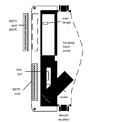
2
Determine which slot will be used for the analog module.* If there is a duct present, and it is different from the one provided in the connector set, then it must be removed.This is accomplished by removing the two screws located on the top and bottom of the housing and then pulling the duct out.
3
If there is a module to the left of this slot, it must be removed until installation of the duct is complete.
4
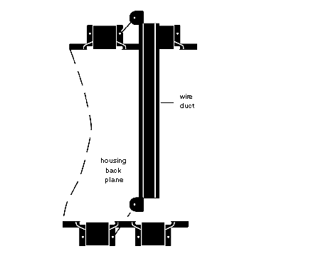
Insert the wire duct between the two slots with the screw holes to the left. (Refer to the installation diagram.)
5
Using the two 1/4 inch slotted screws provided in the package, secure the wire duct to the housing.
6
Re-install the module(s) and complete the wiring connections.
*The wire duct can not be installed for the left-most slot of the housing. Therefore the use of this slot for the analog module is not recommended.