|
B873-002 and B875-002 Calibration
|
|
|
(Original Document)
|
|
1.
|
A programmer
|
|
2.
|
A precision voltmeter
|
|
3.
|
An Analog DC Voltage/Current
|
|
4.
|
A 1/4 inch Phillips screwdriver
|
|
5.
|
A 1/8 inch standard screwdriver
|
|
6.
|
An adhesive for the trim pot adjusting screw (e.g. Locktight Glyptol)
|
|
1.
|
Remove trim pot access cover, located on the front panel.
|
|
2.
|
Open module handle to expose connector(s) and terminal(s).
|
|
3.
|
Unplug field wiring connector(s).
|
|
4.
|
Set up Programmer to monitor the register for the channel used for calibration.
|
|
Method using a voltage source:
|
|
|
5a.
|
Connect the positive lead of the voltage source to the channel's input + terminal and the negative lead to the channel's input - terminal.
|
|
6a.
|
Set voltage source to output 1.00048 volts.
|
|
7a.
|
While monitoring the register, adjust the top trim pot until the value toggles between 0000 and 0001 (Standard) or 4095 and 4096 (Elevated).
|
|
8a.
|
Use an adhesive to secure the adjusting screw on the trimmer.
|
|
9a.
|
Set voltage source to output 4.99951 volts.
|
|
10a.
|
While monitoring the register, adjust the bottom trim pot until the value toggles between 4095 and 4096 (Standard) or 8191 and 8192 (Elevated).
|
|
Method using a current source:*
|
|
|
5b.
|
Connect the positive lead of the current source to the channel's input + terminal and the negative lead to the channel's input - terminal.
|
|
6b.
|
Set current source to output 4.002 mA.
|
|
7b.
|
While monitoring the register, adjust the top trim pot until the value toggles between 0000 and 0001 (Standard) or 4095 and 4096 (Elevated).
|
|
8b.
|
Use an adhesive to secure the adjusting screw on the trimmer.
|
|
9b.
|
Set current source to output 19.998mA.
|
|
10b.
|
While monitoring the register, adjust the bottom trim pot until the value toggles between 4095 and 4096 (Standard) or 8191 and 8192 (Elevated).
|
|
11.
|
Disconnect input source.
|
|
12.
|
Re-connect field wiring.
|
|
13.
|
Close module handle.
|
|
14.
|
Replace trim pot access cover.
|
|
* To use this method, a jumper must be connected between the Current Sense terminal and the Input + terminal of the channel to be calibrated.
|
|

|
Standard
|
Elevated
|
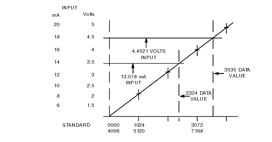
Input Voltage, Current, or Condition
|
|---|---|---|
|
0000
|
0000
|
1. First three seconds after power up
2. During failure recovery
|
|
0000
|
4095
|
Under range
|
|
0000
|
OFF
|
1.0000V or 4 mA
|
|
4095
|
4096
|
4.999V or 19.995 mA
|
|
4095
|
8192
|
Over range
|