|
Calibration
|
|
|
(Original Document)
|
|
Step
|
Action
|
|---|---|
|
1
|
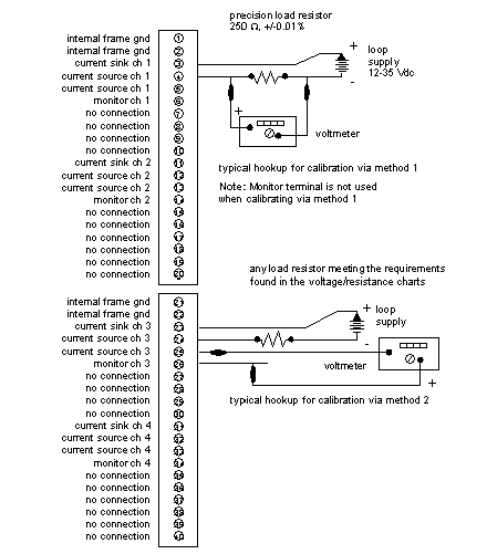
Use a close tolerance 250 W resistor (+/-0.01%) and a voltage supply of between 12 and 35 Vdc. The voltage readings will be taken across the resistor. Connect as indicated in the upper part of the voltmeter connections diagram.
|
|
2
|
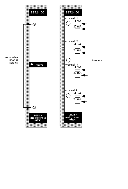
Remove the two screws and the label located on the front panel of the analog output module. This allows you access to the trim-pots. There are two trim-pots per output. The first two trim-pots are for output number one, the second set is for output two, etc. Refer to the figure below for the location of trim pots.
|
|
3
|
Open the analog output module handle to expose the connectors and terminals.
|
|
4
|
Load the data value of 0000 into the output register for the channel under test.
|
|
5
|
Adjust the top (4 mA calibrate) trim-pot of the set for a voltage of +1.0000, +/-0.002 volts. This calibrates to +/-0.05% of full scale.
|
|
6
|
Manually program a data value of 4095 into the output register for channel one.
|
|
7
|
Adjust the bottom (20 mA calibrate) trim-pot of the set for a voltage reading of +4.9990, +/-0.002 volts. This calibrates to +/-0.05% of full scale.
|
|
8
|
Return to step 4 and repeat steps 4-8 until module is within tolerance.
|
|
9
|
Move connections to next channel to calibrate, and repeat steps 4 through 8 for each output channel.
|
|
10
|
After the calibration procedure is complete, disconnect the voltmeter, return connections to their original state, close module handle, and replace front label that covers the trim-pots. pot locking paint, and other substances are not required.
|


|
Step
|
Action
|
|---|---|
|
1
|
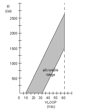
Connect loop supply and load resistor (if any) as indicated in the lower part of the voltmeter connections diagram. Verify that resistor and loop supply are within limits as defined by the voltage resistance chart.
|
|
2
|
Connect voltmeter to monitor terminals as indicated in the lower part of the Voltmeter connections diagram.
|
|
3
|
Load the data value of 0000 into the output register for the channel under test.
|
|
4
|
Adjust the top (4 mA calibrate) trim-pot of the set for a voltage of +1.0000, +/-0.002 volts. This calibrates to +/-0.05% of full scale.
|
|
5
|
Manually program a data value of 4095 into the output register for channel one.
|
|
6
|
Adjust the bottom (20 mA calibrate) trim-pot of the set for a voltage reading of +4.9990, +/-0.002 volts. This calibrates to +/-0.05% of full scale.
|
|
7
|
Return to step 3 and repeat steps 3-6 until module is within tolerance.
|
|
8
|
Move connections to next channel to calibrate, and repeat steps 3 through 7 for each output channel.
|
|
9
|
After the calibration procedure is complete, disconnect the voltmeter, return connections to their original state, close module handle, and replace front label that covers the trim-pots. Pot locking paint, and other substances are not required.
The following figure is the voltage/resistance chart.
 |