|
B872-100 Quick Start Test
|
|
|
(Original Document)
|
|
Step
|
Action
|
|---|---|
|
1
|
Set the 4 position DIP-switch as follows: (viewing the rear of the module when held vertically)
SW1,2,3,&4......Left......RTZ
|
|
2
|
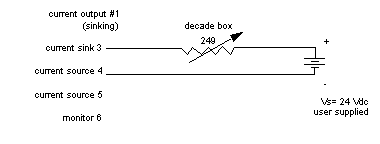
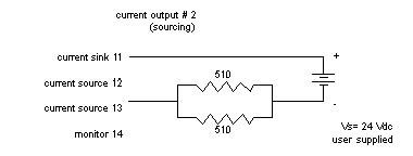
With a resistance decade box, or two paralleled 510 Ω resistors, wire the output module as shown in the following figure, for current sinking, or the next figure, for current sourcing on a AS-8535-000 high density connector.
Note: The resistance decade box should be set for 249 Ω.
Note: Remove the keying tabs on the AS-8535-000 high density connector prior to installing module.
The following figure shows the wiring for current sinking.
 |
|
3
|
Determine which channel and slot location are being used for this module.
|
|
4
|
Stop the controller, and remove AC power.
The following figure illustrates Current Output #2 (sourcing)
 |
|
5
|
Insert the module into the rack.
|
|
6
|
Re-apply AC power, attach programmer, and access the I/O Map.
|
|
7
|
Map the module as a B872, registers 40001-40004 binary.
|
|
8
|
Start the controller.
|
|
9
|
Confirm that the module's active light is illuminated.
Note: Active on steady = OK.
|
|
10
|
Access the programming software. Enter a value of 2048 in any or all of the declared 4xxxx registers in the I/O Map assigned to the module.
|
|
11
|
Using the monitor terminals for each output, measure what should be 3 Vdc. This value is equivalent to 12 mA of current in the loop. Refer to the table below.
|
|
12
|
Continue to provide your output registers with values from Table 2. This assures each output is capable of a span of 4-20 mA.
Note: When using the two resistors in lieu of a decade box, your voltage monitor readings may vary slightly, because of the value and tolerance of the component.
|
|
Register Value
|
Loop Current
|
Monitor Voltage
|
|---|---|---|
|
4xxxx=0001
|
4 mA
|
1.0 V
|
|
4xxxx=1024
|
8 mA
|
2.0 V
|
|
4xxxx=2048
|
12 mA
|
3.0 V
|
|
4xxxx=3071
|
16 mA
|
4.0 V
|
|
4xxxx=4095
|
20 mA-1 LSB
|
5.0 V-1 LSB
|