|
B882–116 24 Vdc Output, Configuration
|
|
|
(Original Document)
|


|
Module Mode Behavior
|
Partial Test Mode
|
Full (PULSE) Test Mode
|
|---|---|---|
|
Use with high speed field devices
|
Yes
|
Not recommended
|
|
Finds opens when OFF
|
Yes
|
Yes
|
|
Finds opens when ON
|
No
|
Yes
|
|
Reaction to OPEN fault*
|
No Change
|
Point OFF
|
|
To clear open fault, close physical fault, then
|
See Note 1
|
Write 0
|
|
Finds shorts when OFF
|
No
|
Yes
|
|
Finds shorts when ON
|
Yes
|
Yes
|
|
Reaction to short fault*
|
Point OFF
|
Point OFF
|
|
To clear short fault, clear physical fault, then
|
See Note 2
|
Write 0
|
|
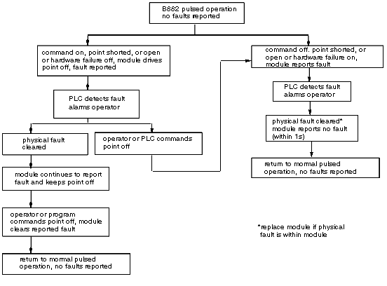
*In all cases faults are reported to the PLC via register entries for corresponding point and type of fault(s). In addition, the fault lamp for the corresponding group will blink until fault indication is cleared. Any points with detected short faults will be turned off independent of the command state from the PLC.
|
||
|
Note 1: In partial test mode an open fault indication will be cleared by writing a 1 to the output point independent of the actual status of the output wiring.
|
||
|
Note 2: In partial test mode a short fault indication will be cleared by writing a 0 to the output point independent of the actual status of the output wiring.
|
||