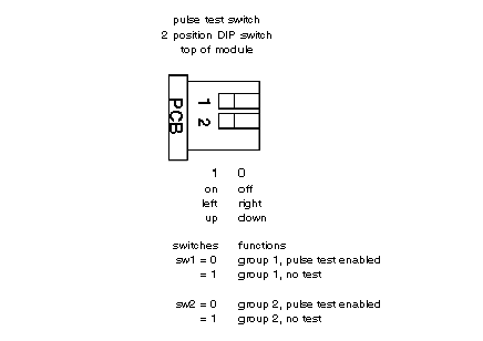
A two-position dip switch located on the rear of the module is used to select one of two test modes on a group basis. No pulse test mode detects open circuits only when the output is off, and shorts circuits only when the point is on.
Pulse test mode pulses the output to the opposite of the command state to determine the status of the output load. Each individual switch relate s to each group of eight output points. For example, DIP switch position #1 when set to on enables pulse test fault sensing for group 1(points 1-8). When a fault is detected the corresponding fault LED flashes independent of the test mode. When the switch is in the off position, no pulse test is performed.
The pulse dip-switch settings for the B882–116 module is shown below.
NOTE: When using binary and BCD format, remember that output 16 is the LSB of word one and word two is ignored by the module.
